
Have you ever wondered what happens after you press “Loop Start”?
When you press the green “CYCLE START” button on the control panel , the machine tool will start moving according to the program.
The whole process seems “magical”—but behind it is a very sophisticated system working together: a component reads the program, a component converts the instructions into electrical signals, a component drives the motor to rotate, a component continuously detects position feedback, and a component controls the coolant and tool changing…
These “parts” are the five core systems of CNC machine tools.
Understanding these five systems is not just about satisfying curiosity—when a machine tool malfunctions, you can roughly determine which part of the process is causing the problem; when you learn more advanced knowledge, you will have a clear framework to understand new content.
System 1: Numerical Control Unit (CNC Controller) – The “Brain” of the Machine Tool
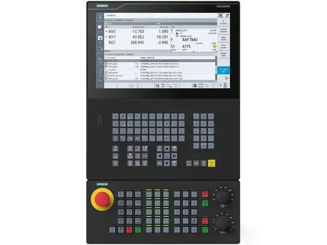
The numerical control device is the core of the entire machine tool; it is what we commonly call the “numerical control system,” also known as the CNC controller.
Its workflow is as follows:
Read program: Read the NC program from memory, CF card, or network interface.
Decoding: Translating G-code, M-code, and other instructions into data that the system can process internally.
Interpolation calculation: Based on the motion command, calculate how much each axis needs to move in each time unit (this is the core calculation – breaking down “from point A to point B” into countless tiny steps).
Issue control commands: Send the motion of each axis to the servo system in the form of electrical signals.
Coordination and auxiliary functions: M-code functions for controlling spindle speed, tool change, coolant, etc.
The CNC device does not only passively execute the program, but also receives position feedback from each axis in real time and corrects motion deviations at any time.
The control panel and display screen you usually see on the machine tool are the human-machine interface of the CNC device—you input programs, modify parameters, and view coordinates through this interface to communicate with the CNC device.
System Two: Servo System – The “Muscles” of the Machine Tool
The CNC device issues a command to “move the X-axis by 0.001mm”, but for this command to be transformed into actual mechanical movement, it relies on the servo system.
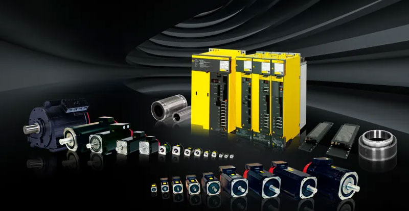
The servo system consists of two parts:
Servo Drive
It receives control signals from the CNC device, amplifies them, and converts them into electrical power to drive the motor. It is essentially a precision “power amplifier”.
Servo Motor
It converts electrical energy into mechanical rotational motion. The difference between a servo motor and a regular motor is that a servo motor has a built-in position encoder, which can precisely control the rotation angle, and its response speed is extremely fast—it can start, stop, or change speed within milliseconds.
CNC machine tools typically have multiple servo systems:
Each of the X, Y , and Z axes has a feed servo: controlling the movement of the tool and the worktable.
Spindle servo: controls the rotational speed of the spindle (tool).
The spindle servo and the feed servo have slightly different focuses: the feed servo pursues positional accuracy (the amount of movement must be precise), while the spindle servo pursues speed stability (the speed must be constant during cutting and cannot fluctuate due to changes in cutting force).
For five-axis machine tools, there are two additional servo systems controlling the rotary axes (A/B/C axes), so there may be a total of 5 to 6 servo systems working simultaneously.
System 3: Machine Tool Mechanical Body – Skeleton and Joints
Servo motors generate rotational motion, but machine tools perform linear movement and rotational positioning of the cutting tools. This requires converting the motor’s rotation into precise movements of various machine tool components, which relies on the mechanical body itself.
The core components of the mechanical body:
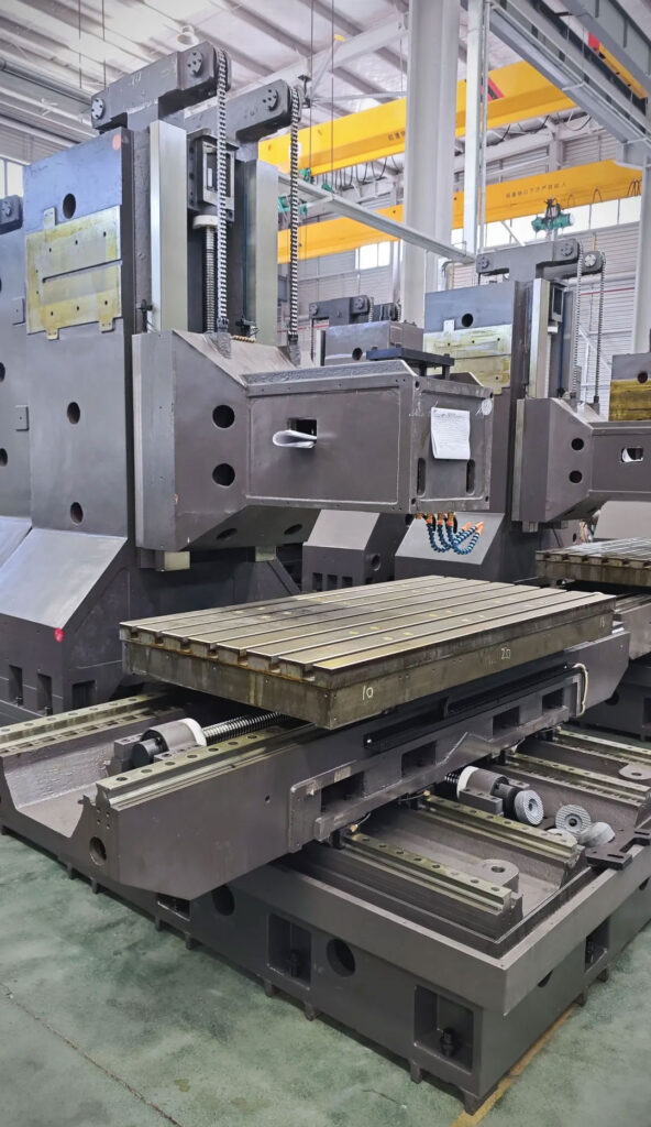
Bed frame
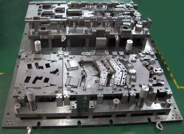
The basic structure of a machine tool is usually made of cast iron or welded steel plates. A good machine bed with high rigidity and good vibration resistance is a prerequisite for ensuring machining accuracy.
Linear guide/way
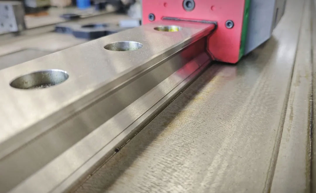
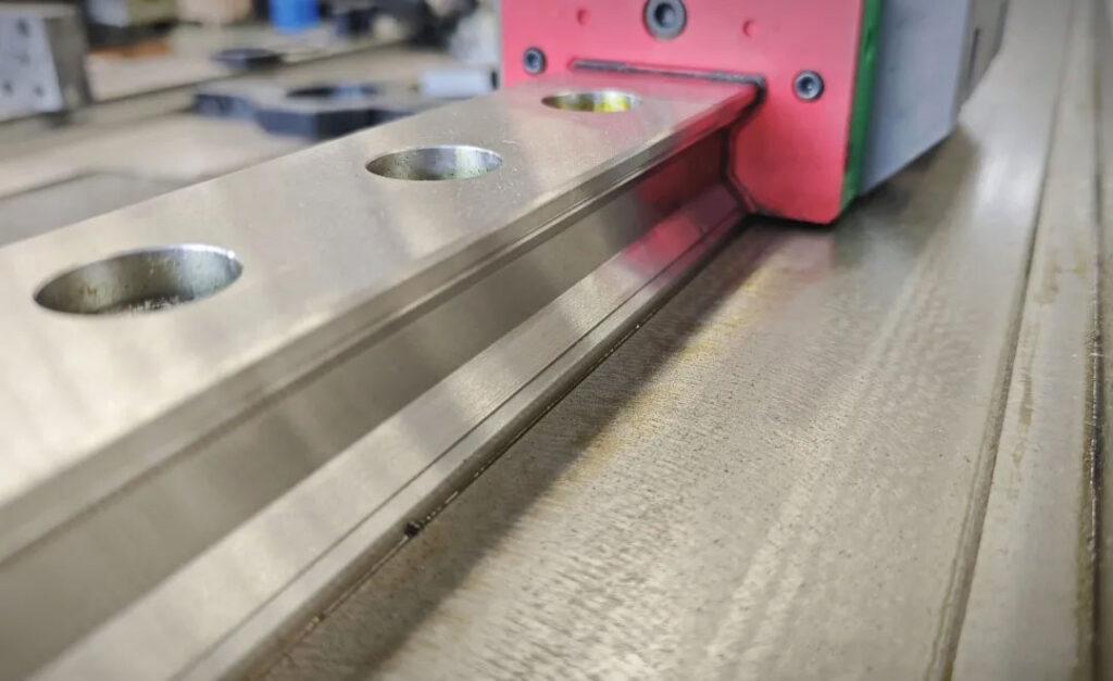
A guide rail is a “track” that guides the worktable and spindle head to move in a specific direction. Modern machining centers generally use linear rolling guide rails, which have low friction, high precision, and fast response. High-precision machine tools use hydrostatic guide rails, which have almost zero friction.
Ball screw
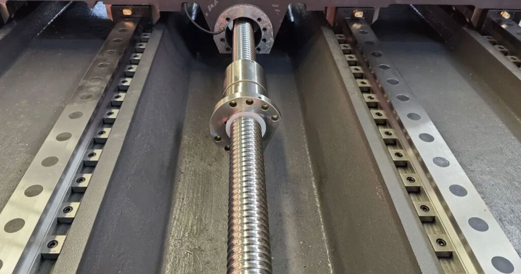
The core component that converts the rotary motion of the servo motor into the linear movement of the worktable. The ball screw transmits force through the rolling of internal steel balls, resulting in minimal friction and enabling micron-level positioning accuracy.
Spindle
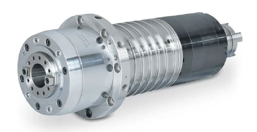
The core component that holds the cutting tool and rotates it at high speed. The accuracy (runout) of the spindle directly affects the machining accuracy, and the maximum spindle speed determines how high a speed you can machine. High-speed spindles can reach 40,000 rpm or even higher.
System Four: Detection Feedback System – The Eyes of Closed-Loop Control
This is a very important system that many beginners don’t understand.
The CNC system tells the servo motor to “rotate 10 times”, but how does it know that the motor actually rotated exactly 10 times? Did the tool actually move the distance you requested?
It relies on the detection feedback system, whose function is to measure the actual position in real time and feed it back to the CNC device so that the system can automatically correct the deviation.
This cycle of “issuing instructions → executing → detecting actual values → comparing deviations → correcting instructions” is called closed-loop control, which is the core mechanism for ensuring CNC accuracy.
There are two common types of detection elements:
Rotary encoder
Mounted on the servo motor shaft, it detects the motor’s rotation angle. Since it detects the motor end rather than the worktable end, errors such as lead screw elastic deformation exist, making it a semi-closed-loop control system. Most machining centers use this approach, with positioning accuracy typically ranging from ±0.005 to 0.01 mm.
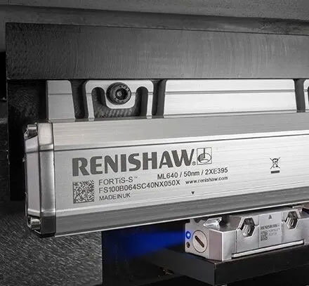
Linear grating ruler
It is installed directly next to the machine tool guideway to measure the actual linear displacement of the worktable. Because it directly measures the worktable position, it eliminates errors in transmission components such as lead screws, and is a fully closed-loop control system with higher accuracy (up to ±0.001mm). High-precision machine tools and precision five-axis machine tools are generally equipped with linear encoders.
System Five: Auxiliary Function System – Enabling Machine Tools to “Get Work Done”
The first four systems work together to ensure precise tool movement. However, to truly complete the machining process, a series of auxiliary functions are also needed:
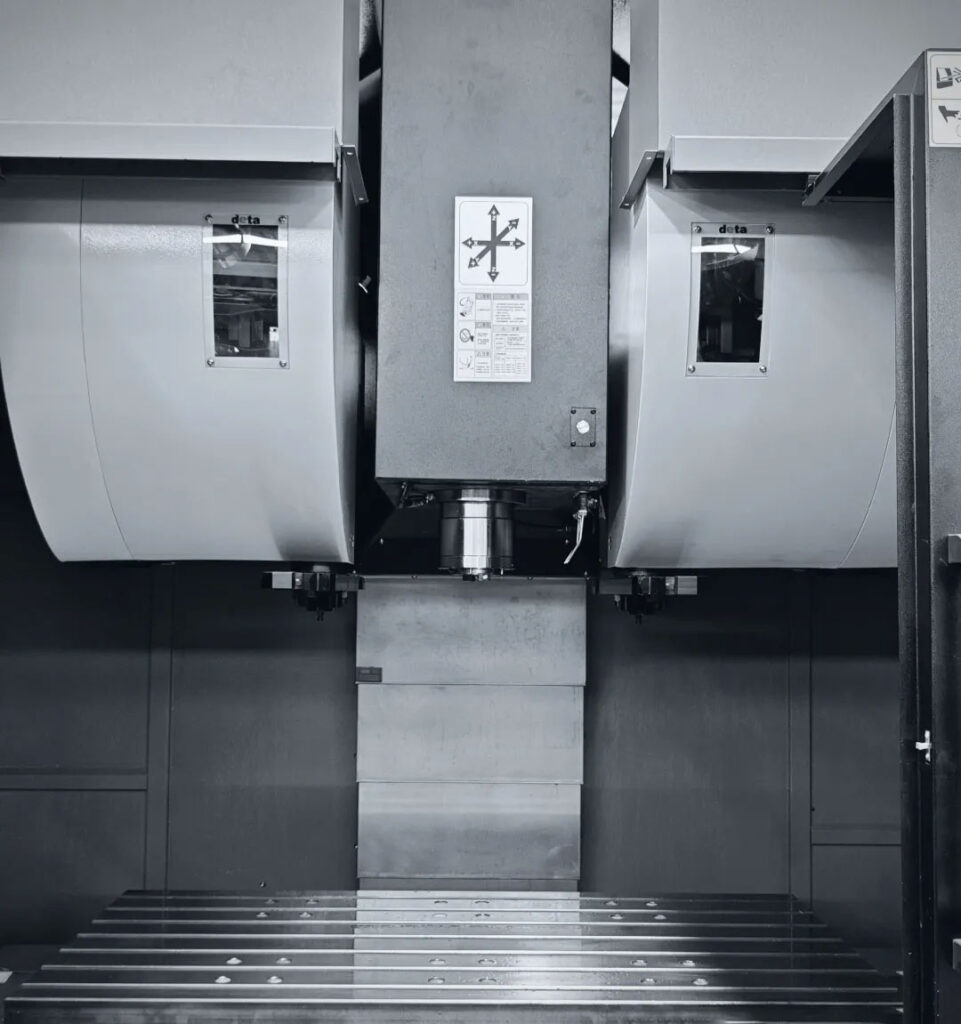
Automatic Tool Changer (ATC) system
One of the most important features of a machining center is its tool magazine, which stores multiple tools. Tool changes are automated by a robotic arm, typically taking only a few seconds. Tool magazine capacities range from 8 to over 100 tools.
Cooling system
During machining, a large amount of heat is generated between the tool and the workpiece. Coolant is responsible for cooling, lubrication, and chip removal. Common methods include external spray cooling and internal cooling (sprayed directly onto the cutting zone through the spindle and tool center hole).
pneumatic/hydraulic system
Used for actions requiring significant force, such as clamping workpieces, changing tools, and releasing tools from the spindle.
PLC (Programmable Logic Controller)
The CNC unit only handles motion control, while the numerous on/off control functions on the machine tool (tool change, coolant switch, safety door interlock, etc.) are handled by the embedded PLC. The PLC and the CNC unit work together to form a complete machine tool control system.
Signal flow of the five major systems:
The entire system’s workflow can be understood using a signal chain:
NC Program Input
↓
CNC Unit (Read → Decode → Interpolation → Output commands)
↓
Servo System (Power amplification → Drive motor rotation)
↓
Auxiliary Functions System (Tool change / Cooling / Hydraulic operations → Controlled by PLC, coordinated with the above processes)
↓
Detection Feedback System (Encoder / Grating scale → Actual position feedback)
↓
Machine Structure (Ball screw → Guide rail → Table movement / Spindle rotation)
This is what happens after “pressing the cycle start button,” a precise closed-loop control process that repeats thousands of times per second.
Introduction to Mainstream CNC System Brands
Having learned about the function of CNC devices, let’s take a look at the major brands on the market:
FANUC: A Japanese brand with the largest global market share and a very high percentage of factories in China. Its systems are stable and reliable, with a well-developed technological ecosystem, making it the top choice for beginners (subsequent operation examples in this series will primarily focus on FANUC).
Siemens SINUM ERIK: A German brand , the mainstream configuration for European machine tools. SINUMERIK ONE is a high-end machine tool system with powerful functions and comprehensive five-axis support, but the learning curve is relatively steep. It has extensive applications in the domestic automotive and aerospace industries.
Heidenhain TNC: A German brand specializing in milling machining centers, offering the most refined five-axis functionality and enjoying a high reputation in the aerospace and precision mold industries.
Chinese brands have developed rapidly in recent years. The following are some of the main representatives:
| Brand | Parent Company | Key Advantages | Market Positioning | 5-Axis Support |
|---|---|---|---|---|
| Huazhong-9 | Huazhong CNC | Domestic CPU, independent and self-controlled | Mid-to-low end, domestic substitution | General |
| GSK | GSK CNC Equipment | Price advantage, complete supporting solutions | Economy-class machine tools | General |
| Kede GNC62 | Kede CNC | 5-axis linkage and mill-turn compound machining | Mid-to-high end | Good |
| SYNTEC | Syntec Technology | Strong CAM compatibility, user-friendly interface, leading domestic 5-axis installation rate | Mid-range, fastest growing in 5-axis field | Good |
Special Focus: SYNTEC System – The Mainstay of Chinese 5-Axis Systems
Among the many Chinese produced CNC systems, SYNTEC has performed particularly well in the field of five-axis machining in recent years, and has become one of the systems with the highest installation rate on domestically produced five-axis machine tools.
The core advantages of the new generation are: extremely strong CAM software compatibility, supporting post-processing output of almost all mainstream CAM software; G-code is basically compatible with FANUC CNC systems, the user interface is user-friendly for beginners, and the learning cost is lower than that of traditional European and American systems; at the same time, it performs stably in key functions such as five-axis RTCP and tool axis control, which is an important reason why many five-axis machine tool manufacturers choose the new generation as their standard system.
If you or your company are planning to buy a Chinese five-axis machine tool, or want to understand the current development status of CNC systems in China, you can pay attention to the Syntec system.
Summary of this article
- Numerical control unit: the brain, which reads programs, performs interpolation calculations, and issues motion commands.
- Servo system: like muscles, driving the precise movement of each axis motor.
- Machine body: frame, bed, guide rails, ball screw, spindle
- Detection feedback system: like an eye, it detects position in real time to achieve closed-loop control.
- Auxiliary function system: Two-hand operation, tool change, coolant, hydraulic and other auxiliary functions