This is a detailed guide from basic concepts to advanced knowledge to help you understand CNC programming systematically.
What is CNC programming?
CNC (Computer Numerical Control) stands for Computer Numerical Control. The essence of CNC programming is to tell a CNC machine how to move the cutting tool to produce the desired part .
You can think of it as:
- Machine Tool : An extremely powerful and precise robot.
- Program (G-code) : The “list of instructions” or “recipe” you write to the robot.
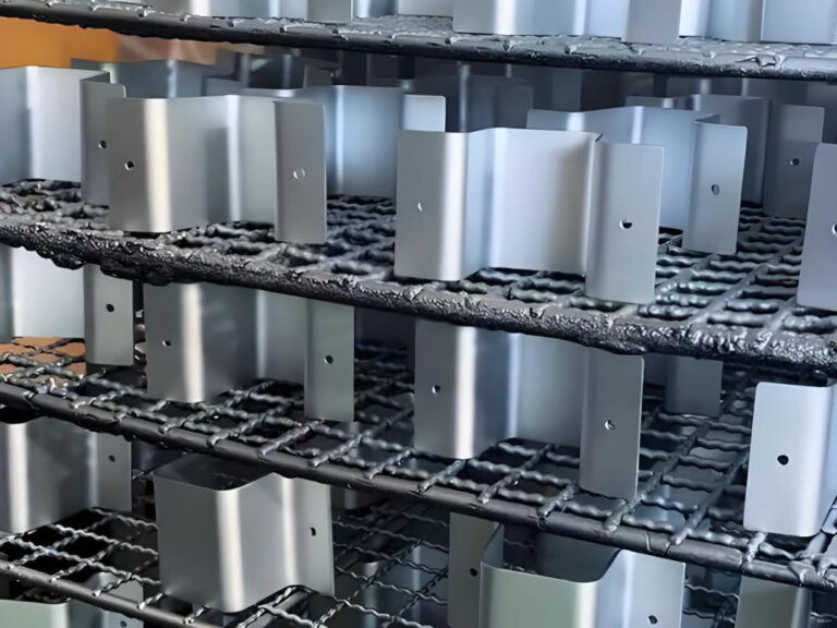
- Raw materials : the ingredients you want to process.
- Finished Parts : The final dish.
It is your job as a programmer to write this “instruction list” to ensure that the machine tool can produce qualified parts safely, efficiently and accurately.
Core components of CNC programming
A complete CNC program usually contains the following key parts:
- Program structure (O prefix and %)
%: Symbols for the start and end of a program.O1234: Program number (e.g. program 1234), which is convenient for searching and calling in the machine tool.
- Safety Settings and Modes (G Code – Preparatory Functions)
G00: Rapid positioning (tool moves quickly without cutting)G01: Linear interpolation (the tool cuts along a straight line)G02/G03: Clockwise/counterclockwise circular interpolationG17/G18/G19: Select XY/ZX/YZ planeG20/G21: Imperial/Metric unitsG40/G41/G42: Tool radius compensation cancel/left compensation/right compensation ( extremely important! )G54-G59: Workpiece coordinate system selection (tells the machine tool where to put the part)
- G codes are instructions that control the movement patterns of machine tools.
- For example:
- Machine tool functions (M codes – auxiliary functions)
M03: Spindle forwardM04:Spindle reverseM05:Spindle stoppedM08: Coolant onM09: Coolant OffM30:The program ends and returns to the program header
- M codes control the auxiliary functions of the machine tool .
- For example:
- Process parameters (S, F)
- S : Spindle speed (unit: RPM, revolutions per minute). For example,
S1200it means the spindle rotates at 1200 rpm. - F : Feed rate (unit: mm/min or inch/min). For example,
F200it means the tool is feeding at a speed of 200 mm/min.
- S : Spindle speed (unit: RPM, revolutions per minute). For example,
- Tool function (T, H, D)
- T : Tool number. For example,
T01it means selecting tool No. 1. - H : Tool length compensation number. For example,
H01it means calling the length compensation value No. 1. - D : Tool radius compensation number. For example,
D01it means calling radius compensation value No. 1.
- T : Tool number. For example,
Two main methods of CNC programming
Method 1: Manual Programming
The programmer uses a text editor (or even Notepad), manually calculates the coordinates (X, Y, Z) of each point on the tool path, and writes the G-code and M-code line by line.
- advantage :
- Have absolute control over the code and a deep understanding of it.
- Suitable for writing simple, point-to-point or repetitive programs (such as drilling a series of holes).
- No need to buy expensive software.
- shortcoming :
- Extremely tedious and error-prone , especially for complex shapes such as free-form surfaces.
- The computation is large and the efficiency is low.
- Difficult to modify and optimize.
Manual programming example (milling a 10x10mm square with a depth of 2mm):
gcode
% O 1000 (SQUARE POCKET PROGRAM) G17 G21 G40 G49 G80 G90 (Safety setting line: XY plane, metric, cancel all compensations) G54 G00 X 0 Y 0 (Select coordinate system, rapid move to origin) M03 S 2000 (Spindle CW, 2000 RPM) G43 Z 10. H 01 (Rapidly lower the tool to Z10 height, call length compensation No. 1) G00 X -5. Y -5. (Rapidly move to starting point) Z 2. (Rapidly lower the tool to Z2) G01 Z -2. F 100 (Feed lower to Z-2 at 100 mm/min) X 5. F 200 (Milling to X5) Y 5. (Milling to Y5) X -5. (Milling to X-5) Y -5. (Milling back to starting point) G00 Z 10. (Rapidly raise the tool) M05 (Spindle stop) M30 (Program end) %
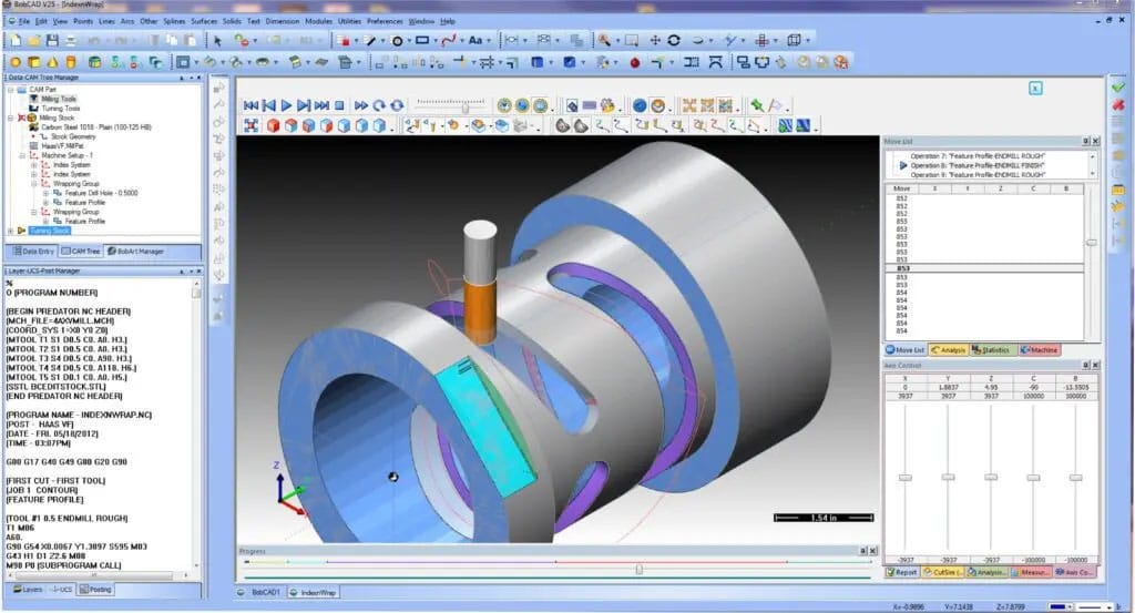
Method 2: CAM software programming (modern mainstream method)
Programming is done using Computer Aided Manufacturing (CAM) software. In the software, programmers:
- Create or import a 3D model (CAD model) of the part.
- Define the stock.
- Select the tool and set the cutting parameters (S, F, cutting depth).
- Select the machining strategy (such as cavity milling, contour milling, drilling, etc.).
- The software automatically calculates the tool path and post-processes it to generate the G-code required for the specific machine tool.
- advantage :
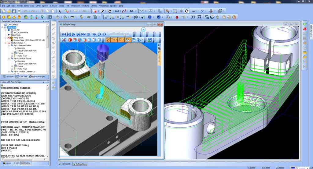
- Efficient and accurate , especially suitable for complex 2D and 3D surfaces.
- Visual simulation allows you to check errors on the computer and avoid tool collisions.
- Easy to modify and optimize the process.
- shortcoming :
- Need to learn and purchase software (such as Mastercam, Fusion 360, PowerMill, UG NX, etc.).
- Programmers still need to have a deep understanding of G code and processing technology to set reasonable parameters.
Common CAM software :
- High-end/professional : Siemens NX, CATIA, PowerMill, HyperMill
- Mid-range/mainstream : Mastercam, GibbsCAM, Cimatron
- Entry/Integration Level (Highly Recommended for Beginners) : Autodesk Fusion 360 (Free Personal Edition, Powerful, Integrated CAD/CAM/CAE)
Basic process of CNC programming
Whether using manual or CAM, the basic logical process is the same:
- Analyze part drawings : understand the geometry, dimensional tolerances and technical requirements of the drawings.
- Process planning :
- Determine the machining steps (what to do first and what to do later? Roughing -> Semi-finishing -> Finishing).
- Select the clamping method (how will the blank be secured? Vise, clamp, fixture?).
- Choose a cutting tool (what kind of tool? What diameter?).
- Determine the cutting parameters (S spindle speed, F feed rate, cutting depth ap, cutting width ae).
- Mathematical processing : Calculate the coordinates of key points in the tool path (required for manual programming, automatically completed by CAM).
- Programming : Manually write or generate G code through CAM software.
- Program verification :
- A crucial step! Use the simulation function of the CAM software or independent machine tool simulation software (such as Vericut) to check whether the program has problems such as overcutting, tool collision, and excessive empty cutting.
- Perform dry runs (running without parts or tools) or test cuts (testing with cheap materials such as wax or wood) on the machine tool .
- Transfer and execute : The verified program is transferred to the machine tool via a USB flash drive, network or DNC for processing.
Learning path suggestions for beginners
- Lay a solid theoretical foundation :
- Learning mechanical drawing : Being able to understand the drawings is the first step.
- Learn metalworking : Understand the properties of materials (steel, aluminum, stainless steel, etc.), cutting tools, and cutting principles. This is the basis for setting reasonable S and F.
- Be familiar with machine tool structure : Understand the basic operation of milling machines and lathes. It is best to practice in a workshop for a period of time.
- Conquering G-code :
- You don’t have to memorize all the codes, but you must master the most commonly used core G/M codes (such as G00, G01, G02/G03, G40/G41/G42, G90/G91, M03/M05/M08/M09/M30).
- Understanding the principle of tool compensation (G41/G42) is a key step from being a novice to becoming an expert.
- Start practicing with CAM software :
- I highly recommend starting with Fusion 360. It’s powerful and free for learners.
- Find some simple models (such as the square groove above) and learn to set up the tool, stock, select the operation and generate code in the CAM module.
- Use the software’s simulation capabilities to double-check your tool paths.
- Combined with practice, continuous optimization :
- Observe the actual machining process of the machine tool, listen to the sound, see the chips, and think about how to optimize the parameters (increasing the speed and feed can improve efficiency, but how to ensure tool life and surface quality?).
- Ask more experienced masters for advice.
Conclusion
CNC programming is the crucial bridge that transforms design intent into physical reality . It is a comprehensive skill that integrates software operation , mechanical theory , and practical experience . Although modern programming is primarily based on CAM software, deep process knowledge and understanding of G-code will always be the core difference between excellent programmers and ordinary operators.