What Is Gantry Machining
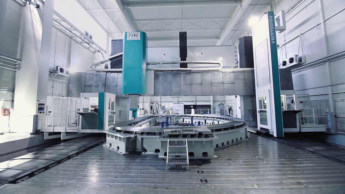
A gantry machining center is a large-scale machining center in which the axis of the spindle Z-axis is arranged perpendicular to the worktable. The overall structure is a gantry-type structural frame composed of double columns and a top beam, with a crossbeam in the middle of the double columns.It is especially suitable for machining large workpieces and workpieces with complex shapes .
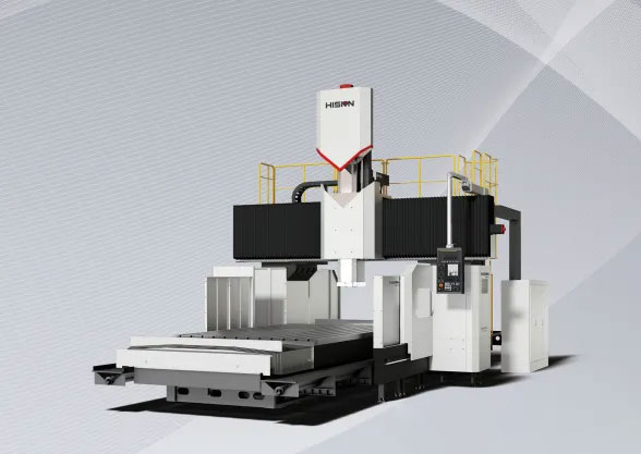
There are various types of gantry machining centers, including fixed-beam (fixed crossbeam, movable/rotating worktable), movable-beam (crossbeam moves up and down, worktable moves forward and backward), movable-column (worktable fixed, gantry moves), overhead crane (worktable fixed, crossbeam moves), and combinations of these. Each type of gantry machining center has different machining characteristics, capabilities, and intended product applications.
Gantry Machining Centers vs. Standard Machining Centers: Key Differences
First, in terms of structure, the gantry machining center has a very long X-axis, a double-column structure, a larger Y-axis stroke than ordinary machining centers, and an additional side milling head.
Secondly, in terms of processing range, the gantry machining center has obvious advantages in heavy cutting due to its double-column support, so it can process larger workpieces. Some larger or more complex workpieces can only be processed by the gantry machining center, which cannot be processed by ordinary machining centers.
Again, in terms of size, gantry machining centers are usually larger than ordinary machining centers.
How to select a gantry machining center?
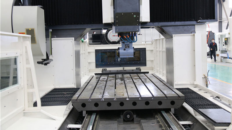
- Select machine tool specifications and worktable dimensions. Determine the required machine tool worktable dimensions and the travel of the three linear coordinate systems based on the size of the workpiece. The worktable dimensions should ensure smooth clamping of the workpiece, and the machining dimensions must be within the travel of each coordinate system. Furthermore, consider the tool change space and the interference zone restrictions of each coordinate system.
- Select the tool magazine capacity. The required number can be determined based on the process analysis of the workpiece being machined. Typically, the tool magazine capacity is determined by the number of tools required for a single clamping of a part. This is because when machining another part, tools must be rearranged, making tool management complex and prone to errors.
- Selection of the workpiece. Generally speaking, parts with the following characteristics are suitable for machining in a machining center: workpieces requiring intensive multi-processing, workpieces requiring complex positioning, and workpieces requiring repetitive production. Furthermore, even if the workpieces vary in shape and size, similar workpieces are more amenable to group machining (GT).
- Select machine tool functions and accessories. The selection functions are mainly for the CNC system, and also include: square T-type ram, spindle gearbox, spindle oil cooler, spindle center water outlet, fully automatic right-angle, dual-output, universal angle milling head, etc.
- Selection of machine tool accuracy: Users should select machine tools with corresponding accuracy levels based on the machining accuracy requirements of the workpiece.
Operating procedures of gantry machining center
- The operator should be familiar with the performance and characteristics of the gantry machining center. Ensure that the emergency stop switch can play a role quickly and effectively in an emergency to avoid injury accidents.
- Wear labor protection equipment as required and it is strictly forbidden to operate with gloves.
- When the equipment is working, do not touch the electronic switch with wet hands to avoid electric shock. Do not touch any moving parts with your hands.
- Do not place tools or non-processed workpieces on the gantry machining center or moving objects.
- The computer table or work table next to the machine must be sturdy and must not be placed on moving parts.
- When loading or unloading workpieces, the machine should be stopped first and the workpiece should be kept at a proper distance from the tool. Do not open the front door and left and right covers while the machine is running to avoid personal injury.
- After the tool is set, please run it with DRY RUN to confirm that the program is correct.
- When shutting down after a power outage or emergency stop, the three axes should be restored to their original mechanical positions.
- Do not remove the travel switch or any related parts of the protective switch without authorization.
- Before leaving the machine after finishing work, turn off the control power switch on the operation panel and the main switch of the electrical box.
Reasons For The Deterioration Of Accuracy And Solutions
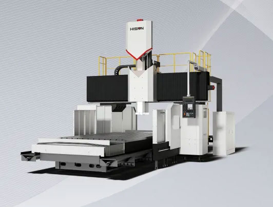
Since the gantry machining center has a relatively high operating accuracy, it is often used to process large parts. However, after a long period of operation, the accuracy of the machining center may deteriorate, which will seriously affect normal work. Therefore, the following introduces the specific reasons for the deterioration of accuracy and solutions.
Roundness deviation when two axes of gantry machining center are linked
1. Axial deformation of the circle may be caused by improper mechanical adjustment. Poor axis positioning accuracy or improper compensation of the screw clearance will cause roundness error when passing through the quadrant.
2. For skew elliptical error (an ellipse at 45 degrees), first check the position deviation of each axis of the gantry machining center. If the deviation is too large, adjust the position loop gain to eliminate it. Next, check whether the interface board of the rotary driver or induction synchronizer is properly adjusted. Finally, check whether the mechanical transmission backlash is excessive and whether the backlash compensation is appropriate.
The machining accuracy of gantry machining center parts is poor
This is usually caused by improper adjustment of the feed dynamics between the axes during installation or by changes in the drive train of the machine’s axes due to wear and tear. Check whether the servo motor speed is too high, whether the position detection element is in good condition, whether the position feedback cable connector is in good contact, whether the corresponding analog output latch and gain potentiometer are in good condition, and whether the corresponding servo drive is functioning properly.
Overshoot during movement of the gantry machining center causes poor machining accuracy
The acceleration and deceleration time may be too short, so the speed change time can be appropriately extended; the connection between the servo motor and the screw may be loose or the rigidity is too poor, so the gain of the position loop can be appropriately reduced.
The accuracy problems of the gantry machining center are mostly due to problems with its own parts or inadequate adjustment of the movement time. When we find that there is a problem with the precision reading, we must stop working as soon as possible to adjust and solve the relevant problems to ensure that the accuracy can be restored in the next work so that the work can be carried out smoothly.


