Intro
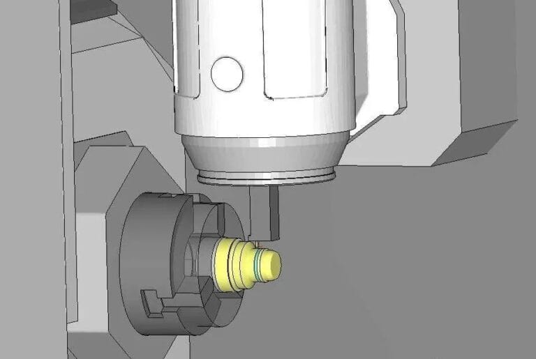
In CNC machining, the rotation direction of the milling cutter is generally constant, but the feed direction is variable. This results in two common phenomena in milling: down milling and up milling.
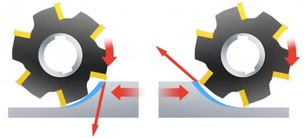
The cutting edge of a milling cutter is subject to impact loads every time it cuts in. For successful milling, the correct contact between the cutting edge and the material must be considered during both the entry and exit phases of a cut. During milling, the workpiece is fed in the same or opposite direction as the milling cutter’s rotation, which influences the entry and exit phases, as well as whether down-cut or up-cut milling is used.
The golden rule of milling – from thick to thin
When milling, always consider chip formation. The position of the milling cutter is crucial to chip formation, and you should aim for thick chips as the cutter enters the milling process and thin chips as the cutter exits the milling process to ensure a stable milling process. Remember the golden rule of milling, “thick to thin,” to ensure the smallest possible chip thickness as the cutter exits the milling process
Climb milling
In climb milling, the cutting tool is fed in the direction of rotation. Whenever the machine tool, fixture and workpiece allow, climb milling is always the preferred method.
In edge milling, the chip thickness decreases from the beginning of the cut to zero at the end of the cut. This prevents the cutting edge from scraping and rubbing against the part surface before it engages in cutting.
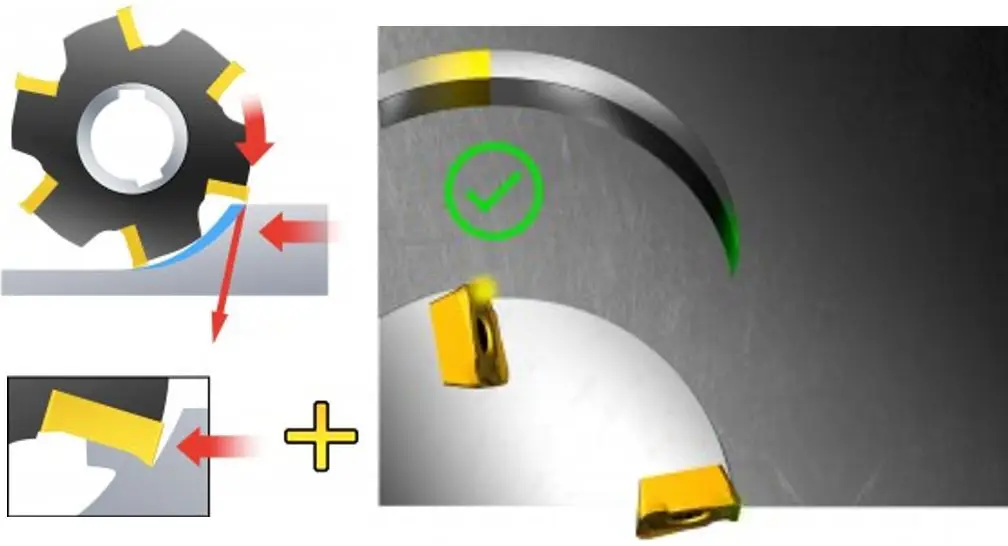
Large chip thickness is advantageous, as cutting forces tend to pull the workpiece into the cutter, keeping the cutting edge in the cut. However, because the cutter tends to be drawn into the workpiece, the machine tool needs to handle table feed clearance by eliminating backlash. If the cutter is drawn into the workpiece, the feed will increase unexpectedly, potentially leading to excessive chip thickness and broken cutting edges. In these cases, consider using up-cut milling.
Up milling
In up-cut milling, the cutting tool is fed in the opposite direction to its rotation.
Chip thickness starts at zero and gradually increases until the end of the cut. The cutting edge must be forced into the cut, causing a scratching or polishing effect due to friction, high temperatures, and constant contact with the work-hardened surface created by the previous cutting edge. All of this shortens tool life.
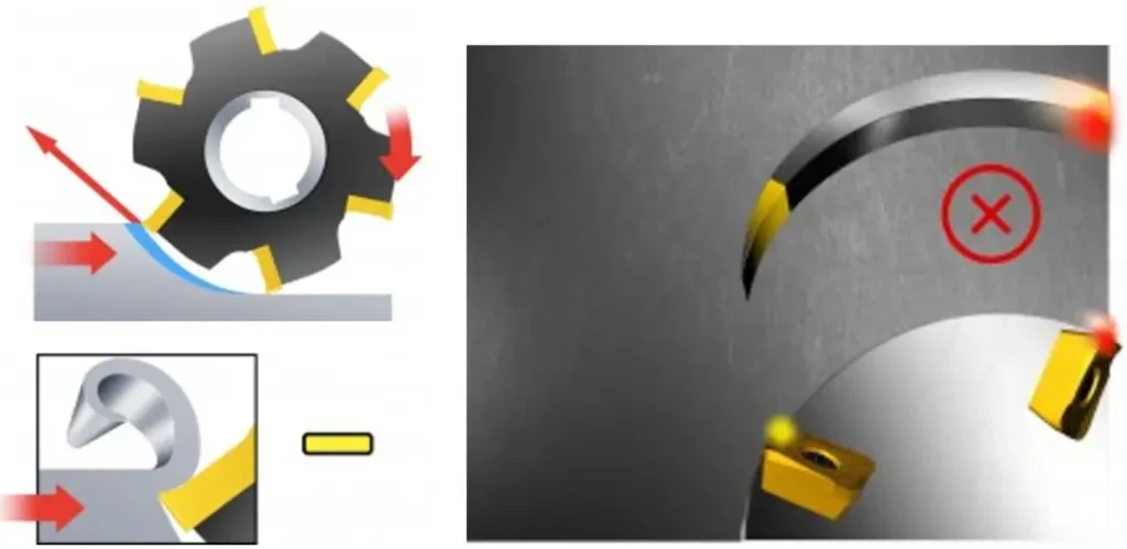
The thick chips and high temperatures generated when the cutting edge exits the cut will cause high tensile stresses, which will shorten tool life and the cutting edge will usually deteriorate rapidly. It may also cause the chip to stick or weld to the cutting edge, which will then carry it to the start of the next cut, or cause the cutting edge to break instantly.
Cutting forces tend to push the cutter and workpiece away from each other, while radial forces tend to lift the workpiece from the worktable.
When there are large changes in machining allowance, up-cut milling may be more advantageous. It is also recommended when machining high-temperature alloys with ceramic inserts because ceramics are more sensitive to the impact generated when cutting into the workpiece.
Workpiece fixture
The feed direction of the tool places different demands on the workpiece fixture. During up-cut milling, it should be able to resist the lifting force. During down-cut milling, it should be able to resist the downward force.
Comparison table of down milling and up milling
| Item | Climb Milling | Conventional Milling |
|---|---|---|
| Chip Thickness | Large to Small | Small to Large |
| Slipping Phenomenon | No | Yes |
| Tool Wear | Slow | Fast |
| Work Hardening | No | Yes |
| Effect on Workpiece | Presses Down | Lifts Up |
| Eliminates Screw and Nut Backlash | No | Yes |
| Vibration | Large | Small |
| Energy Consumption | Low | High (5% to 15% more) |
| Surface Roughness | Good | Poor |
| Applicable Scenario | Finishing | Roughing |