Introduction
It is known to form a variety of shapes within a workpiece, whether it is a complex contour, groove or precise hole. One common contour is a groove to accommodate a key, seal or other functional component.
What about slot milling operations? Is it as simple as conventional face milling? What machine tools are used? How do machinists solve chip evacuation and tool deflection issues?
This article will walk you through the slot milling process, explaining the basic techniques used to create slots. We will also discuss specialized milling tools designed for the task and specific applications where slot milling cutters play a key role.
What is slot milling?
A slot is a narrow, elongated channel milled into a workpiece for different functional purposes. It may accommodate a fastener, guide a mechanical component or facilitate the assembly process.
Grooving is the process of creating channels, slots or grooves in a workpiece using a rotating cutting tool. The shapes and sizes of these slots can vary depending on the design requirements. They may be closed, straight (rectangular) or curved (circular) and may exist as single slots or in pairs.
Performance
It helps to achieve high-precision grooves, channels or keyways.
Allows creation of complex geometries.
Ensure part fit and function with custom solutions.
Suitable for a variety of materials.
limit
Risk of tool deflection in deep and narrow grooves.
T-slot milling techniques and types of slot cutting tools
Milling a slot is the ultimate goal – and this slot can be created using different slot cutting cutters and techniques. The choice of method depends on the desired slot features and its intended application.
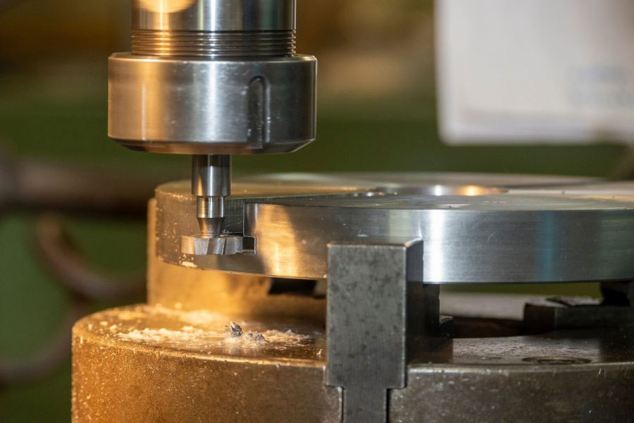
End milling
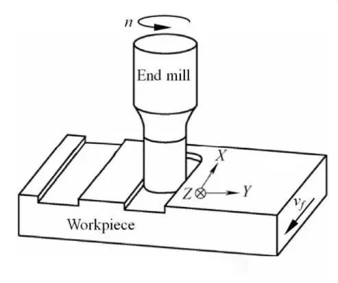
End milling is performed with an end mill, which has cutting edges on the end face and periphery. The end mill is fed into the workpiece along its axis to carve a slot width that matches the width of the tool.
End mills are common and come in standard sizes and depths. Therefore, they are the first choice for machinists to create slots.
Their greatest strength is their design versatility: they can produce nonlinear paths, variable depths, and even closed slots (e.g., pockets in a mold cavity).
Face milling
Milling cutters are primarily designed to cut to create flat surfaces with their peripheral teeth. However, they can also create shallow linear grooves in large, flat workpieces.
Unlike end mills, they excel at high-volume material removal over wide areas, such as roughing out coolant passages in an engine block. Their larger cutting diameters provide stability, but they lack precision for narrow or deep grooves.
T-Slot Milling Cutter
T-slot milling cutters are designed specifically to create T-slot profiles and are often used in milling machine tables or workholding systems to secure fixtures.
The process is a two-step process: First, a standard end mill cuts the vertical slot, then a T-slot mill (with a horizontal cutting profile) machines the undercut to create the “T” shape.
Half round key cutter

Woodruff key cutters are small, disc-shaped tools with teeth on the edges that are used to machine semicircular grooves. These curved grooves accommodate woodruff keys, which are used to secure power transmission or load-bearing components. Gears are also secured to shafts via these grooves.
Milling
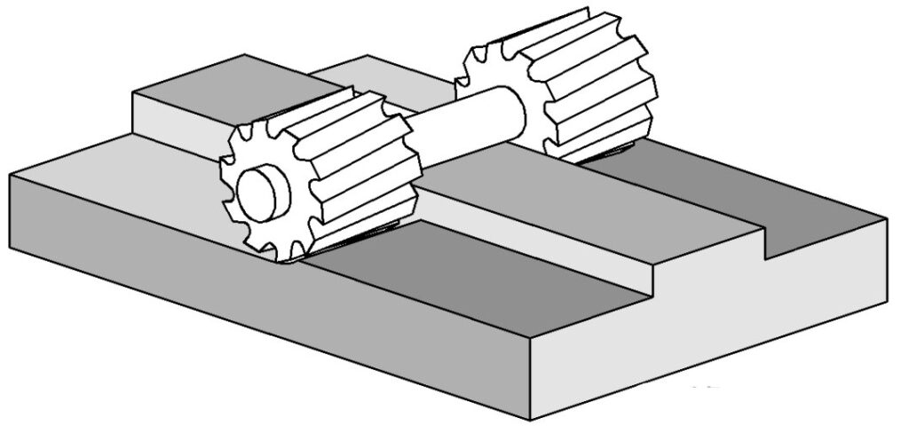
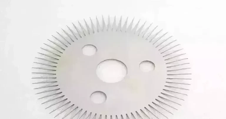
Gang milling is a group milling technique where multiple cutters are mounted on a single spindle to machine multiple slots simultaneously. In most cases, a pair of cutters is used to carve two parallel slots. Fin structures can also be made by gang milling.
Due to the high material removal rates, the technology is well suited to high-volume production. Here, the intense cutting forces require a rigid tool setup to prevent vibration or misalignment.
Slot milling cutter path
There are many ways a slot mill or milling cutter enters a workpiece and performs its work. There are three main basic tool paths that are common in the industry. Each has its own unique uses and advantages:
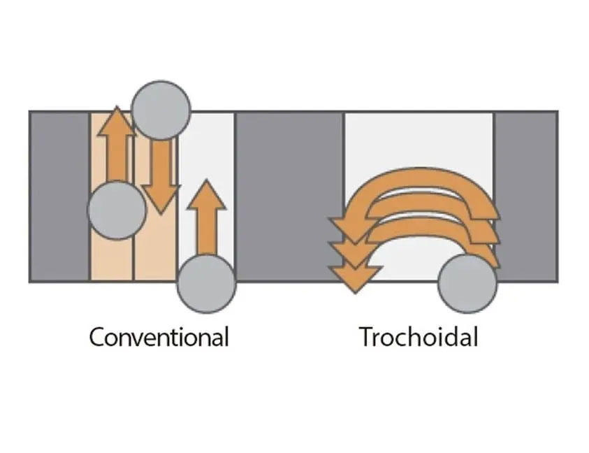
Normal speed
This is the typical method of milling on a workpiece. The tool enters from one side and makes linear cuts along the slot axis. This toolpath works with most common cutters, is easier to program, and is suitable for shallow slot depths.
However, it is less suitable for deeper grooves (eg, grooves deeper than 3xD) because the higher vibrations and radial forces can deflect the tool or damage the workpiece.
Plunge
The plunge milling operation is similar to drilling: the tool (slot drill) penetrates the workpiece axially. Although this method sacrifices surface accuracy, it shines when cutting deep grooves.
The benefit is that axial and radial forces on the tool are reduced, minimizing the risk of deflection. This makes plunge milling ideal for deep grooves in hard materials such as titanium, where tool stability is critical.
Cycloid
In trochoidal grooving, the tool performs a dedicated spiral or circular motion along the cutting path. This method allows a single tool to machine grooves wider than the tool diameter with relatively low radial forces and better chip evacuation.
It is well suited for machining hard materials such as stainless steel or Inconel. However, trochoidal paths are complex to program and usually require advanced CAM software. A final finishing operation may also be required to smooth out the spiral marks left by the tool path.
Best Practices for Slot Milling
In theory, slot cutting seems easy, but machinists often face multiple challenges when slotting. For a successful milling operation, we recommend following these best practices.
Optimizing tool entry with ramp milling
Sudden entry into the workpiece can shock the tool, causing it to chip or deflect. Instead, use a ramp down (gradually lowering the tool at an angle) to evenly distribute the cutting forces. A 45° ramp angle is sufficient to prevent overloading the tool.
For deep grooves or hard materials, a 180° axial cut, similar to drilling, reduces radial forces and prevents tool overload. This approach not only extends tool life, but also avoids catastrophic tool breakage during the cut.
Chip evacuation strategy
Chips stuck in the slot can ruin the finish by cutting back into the workpiece or clogging the chip flutes. One way to address this is through multiple milling passes. Remove material in layers (e.g., roughing at 70% depth, followed by finishing). This gives the chips room to escape the slot walls.
Another option is to use an end mill with a serrated edge or variable helix angle to break the chips into more manageable pieces. Use it with high-pressure coolant or compressed air to flush the chips, especially in closed slots.
Use a larger diameter tool
Given the greater cutting forces and deeper slots, a larger diameter cutter is required to prevent deflection due to the long overhang. The larger the diameter, the greater the strength, which is ideal for this specialized work.
Up and down milling
Climb milling (where the tool rotates in the same direction as the feed) is the preferred method for slotting. It reduces tool wear and improves surface finish because the cutting forces push the workpiece downward, minimizing vibration. This is useful for thin-walled parts or materials that tend to burr.
Spindle engagement
Interrupted cutting can leave pits in the groove surface, resulting in a poor surface quality. It also wastes time without increasing speed. To avoid this, make sure at least one tooth of the tool is always cutting the workpiece.
Slot Milling Applications
Slots play an important role in products across a wide range of industries. The table below lists some of the industrial sectors and specific slot milling applications:
| Purpose | application | industry |
| Alignment and connection | Keyway on gear/pulley shaft T-slot in clamp/fixture for clamping | Automotive, Tools and Fixtures |
| Material Removal | AerospaceWeight reduction slots in ribs/sparsCooling vents in brake rotors and drains in castings. | Aerospace, automotive, general manufacturing |
| Fluid/gas flow | Oil passages in the engine block/shaft Air flow passages in the electronics housing. | Manufacturing and Electronics |
| Precision Parts | Internal gear teeth in gear blanks Lead screw tracks in medical devices | Automobiles, medical equipment, electronics |
| Structural Integrity | Spline shaft for gear meshing Clearance grooves for sliding shafts Grooves in semiconductor wafers | Automobile and electronic |