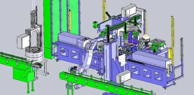

Injection molding machine
TPU materials can be molded using standard screw injection molding machines, and plunger injection molding machines are also suitable. However, for larger parts, a reciprocating screw injection molding machine is recommended. The optimal injection molding machine capacity should be 40% greater than the molded product volume.
Injection molding process
Molding temperature:The injection molding temperature of TPU is mainly determined by the hardness. Table 1 is the reference molding temperature. When customers process, they must adjust it according to the type of injection molding machine, screw type, screw speed, mold pattern design, etc. Customers need to refer to the molding temperature given in Table 1 and make adjustments.
Table 1 TPU Molding Temperature Reference
| Hardness (Shore A) | Rear Part | Middle Part | Front Part | Nozzle |
|---|---|---|---|---|
| 70 | 130℃ | 150℃ | 160℃ | 160℃ |
| 80 | 150℃ | 170℃ | 180℃ | 175℃ |
| 85 | 160℃ | 175℃ | 180℃ | 180℃ |
| 90 | 160℃ | 180℃ | 190℃ | 185℃ |
| 95 | 170℃ | 190℃ | 200℃ | 195℃ |
| 98 | 180℃ | 195℃ | 210℃ | 200℃ |
Compared to soft PVC and ABS, TPU’s melt viscosity is more dependent on temperature. Excessively high temperatures reduce viscosity, making the resin more fluid and prone to defects such as flash, voids, and shrinkage. Excessively low temperatures increase viscosity, making it difficult to flow, which can lead to underfilling and imperfect molded parts.
Processing parameters: Except for the injection molding temperature, other processing parameters refer to Table 2.
Table 2 Injection Molding Process Parameters Reference
| Item | Operating Conditions |
|---|---|
| Injection Pressure | 80~120 kgf/cm² (Gauge Pressure 70~110 kgf/cm²) |
| Injection Speed | Slower than general-purpose resins |
| Screw Rotation Speed | 50~100 rpm |
| Back Pressure | 6~24 kgf/cm² (Gauge Pressure 5~20 kgf/cm²) |
| Holding Pressure | 60~80 kgf/cm² (Gauge Pressure 50~70 kgf/cm²) |
| Cooling Time | 1.2~2 times that of general-purpose resins |
| Mold Temperature | Generally room temperature |
Injection speed: Generally, low-speed injection can be used, with an injection time of 15 to 20 seconds. The first pressure action is about 10 seconds, and the second pressure action is increased by another 5 to 10 seconds. It is 1.5 to 2 times that of general-purpose resins. The lower the hardness of TPU, the longer the injection time.
Depending on the mold temperature, material, and pattern design, the cooling time may need to be increased by 20 to 40 seconds, which is 1.5 to 2 times longer than that of general-purpose resins.
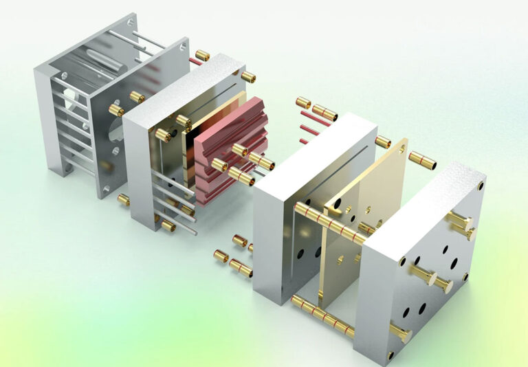
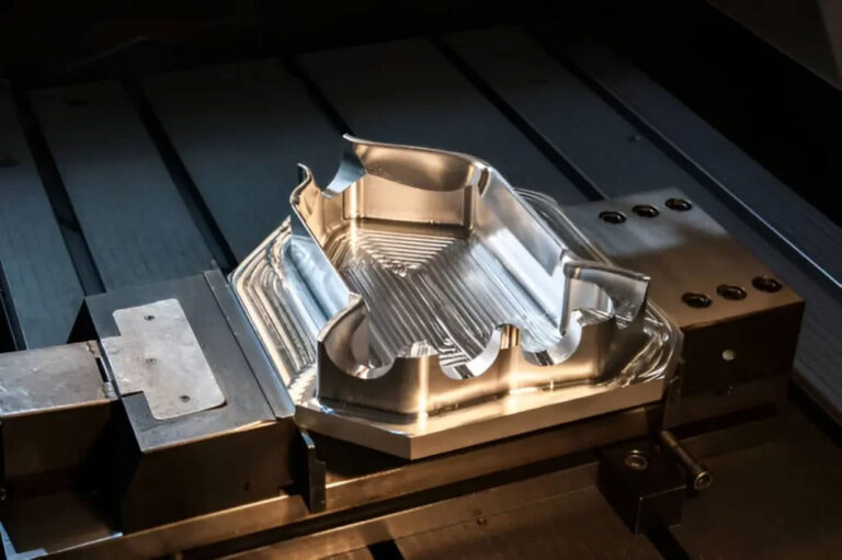
mold
Mold temperature:The mold temperature is best controlled at 20-40°C, and water circulation is recommended. For thin sheet products with large surface area and small cross-sectional area, the mold generally needs to be heated to 40-60°C for molding.
Gates, runners, and orifices: TPU has no specific restrictions regarding gates, runners, and orifices. Rectangular, circular, and semicircular runners are all acceptable. Molds with coarse gates and large inclination angles facilitate demolding. Generally speaking, gates, runners, and orifices should be larger than those used for general-purpose resins. However, when using point-shaped orifices, the diameter should be larger than 0.7 mm. Otherwise, the resin will not fill properly, resulting in a poorly finished product. Figure 3 shows a reference diagram for orifice dimensions, using the relationship between the weight of a WHT-1190 molded part and the cross-sectional area of the orifice.
Demolder: The demoulding device can be a sleeve type, and it is very effective to open a venting groove on the demoulding device.
exhaust: In TPU injection molding, degassing is crucial. Inadequate degassing can lead to scarring, air bubbles, and other issues. Generally, grooves 0.02-0.05 mm wide and deep can be created on the mold’s parting surface, inserts, and ejector pins.
Molding shrinkage
Generally speaking, shrinkage is greatly affected by mold material, product shape, molding conditions, and mold structure. The data given in Table 3 are only used as reference values for mold design.
Table 3 Reference Values for Molding Shrinkage Rate
| Hardness | Shrinkage (%) | Hardness | Shrinkage (%) |
|---|---|---|---|
| Shore A 70 | 2.1 | Shore A 98 | 1.2 |
| Shore A 80 | 1.8 | Shore D 60 | 1.1 |
| Shore A 85 | 1.0 | Shore D 65 | 1.0 |
| Shore A 90 | 0.8 | Shore D 70 | 0.8 |
| Shore A 95 | 1.0 | Shore D 75 | 0.7 |
Causes and solutions for poor injection molding
| Phenomenon | Cause | Solution |
| Bubbles | Moisture in the resin | Ensure thorough drying |
| Excessive molding temperature | Reduce temperature | |
| Insufficient molding pressure | Increase pressure | |
| Insufficient plasticizing back pressure | Increase back pressure | |
| Excessive dead zones in the molded product | Optimize product design | |
| Improper gate location | Improve gate design | |
| Poor venting | Add venting channels |
| Phenomenon | Cause | Solution |
| Sink Marks | Insufficient molding pressure | Increase pressure |
| Insufficient injection volume | Increase injection volume | |
| Excessive molding temperature | Reduce temperature | |
| Injection speed too fast | Reduce speed | |
| Inappropriate product thickness | Optimize thickness dimension | |
| Improper gate size | Adjust gate size | |
| Incomplete venting | Improve venting | |
| Weld Lines / Flow Marks | Slow injection speed | Increase injection speed |
| Incomplete venting | Improve venting | |
| Low mold temperature | Increase mold temperature | |
| Excessive mold release agent | Reduce mold release agent usage |
| Cause | Solution |
|---|---|
| Low injection pressure | Increase injection pressure |
| Insufficient feeding | Increase feeding |
| Insufficient molding pressure | Increase pressure |
| Low injection volume | Increase injection volume |
| Low resin temperature | Increase resin temperature |
| Small gate/runner/sprue size | Improve runner dimensions |
| Low mold temperature | Increase mold temperature |
| Low resin temperature | Increase resin temperature |
| Low injection speed | Increase injection speed |
| Flow marks | Improve flow marks |
| Insufficient holding pressure | Increase holding pressure |
| Low mold temperature | Increase mold temperature |
| Phenomenon | Cause | Solution |
| Flow Marks | Low injection volume | Increase feeding |
| Insufficient feeding | Increase feeding | |
| Insufficient molding pressure | Increase pressure | |
| Low resin temperature | Increase resin temperature | |
| Small gate/runner/sprue size | Improve runner dimensions | |
| Low mold temperature | Increase mold temperature |
| Phenomenon | Cause | Solution |
| Ejection Failure | High molding pressure | Reduce molding pressure |
| High mold temperature | Reduce mold temperature | |
| Short molding cycle | Increase molding time | |
| Small sprue taper angle | Improve sprue taper angle | |
| Short runner length | Lengthen the runner | |
| Insufficient ejection space | Increase ejection space |
Interruption, termination and cleaning of molding machine operation
When temporarily suspending operation, the injection molding machine must be turned off to allow the barrel temperature to cool. At the end of the operation, as with ordinary resins, do not allow plasticized resin to remain in the barrel. Thoroughly clean it and replace the barrel with low-density polyethylene (melt index MI approximately 30-40) or ABS resin.
When changing color and cleaning the barrel, it is most effective to use high-density polyethylene with high melt viscosity (melt index MI less than 10).