Intro
Sheet metal parts are the basic components of a car’s shape, and their appearance largely depends on them. Just like a woman’s figure, many women exercise every day to maintain their figure, persevering and meticulously crafting their bodies. Similarly, the design of sheet metal parts requires good structural design and exquisite craftsmanship.
today
Let’s take a look together.
Sheet metal parts structural design specifications and process rationality requirements
Sheet metal parts are currently the most important and common type of structural component design. They are made from sheet metal materials through stamping. The rationality of the geometry, dimensions, and processing accuracy of sheet metal parts directly affects the processing technology of the parts, which in turn restricts the materials, processes, mold life, product quality, and product cost.

The basic processing methods for sheet metal parts currently include: punching , bending , stretching , and forming. Below, we’ve compiled several sheet metal processing methods for your reference and guidance in sheet metal part structural design.
I, Punching
Blanking is divided into ordinary blanking and precision blanking. Currently, ordinary blanking is commonly used in structural components of electronic communication products. The blanking processes listed below refer to the structural manufacturability of ordinary blanking.
1,The shape and size of the stamped parts should be as simple and symmetrical as possible
The simple and symmetrical shape and size of the stamped parts can minimize waste during the stamping and layout process, which is conducive to saving materials.
2, Sharp corners should be avoided in the shape and inner hole of the stamped part
For the shape and inner hole of the stamped part, the connection between the straight line or curve should be a rounded transition, usually with the radius of the rounded arc R≥0.5t (t is the material thickness).
3, Narrow, long cantilevered or grooved parts should be avoided in stamping
The length and width of the protruding or recessed parts of the stamped parts should generally be greater than 1.5t (t is the material thickness). At the same time, narrow and long cuts and excessively narrow grooves should be avoided to increase the edge strength of the corresponding cut parts of the die, improve the die life, and reduce the difficulty of die processing.
4, Punch shape and minimum size requirements
The shape of the punch should preferably be round, and the minimum punch size is related to the shape of the hole, the mechanical properties of the material, and the thickness of the material.
Minimum punching size
| Material | Round Hole Diameter b | Rectangular Hole Short Side Width b |
|---|---|---|
| High Carbon Steel | 1.3t | 1.0t |
| Low Carbon Steel, Brass | 1.0t | 0.7t |
| Aluminum | 0.8t | 0.5t |
5, Hole spacing and hole edge distance in punching
The minimum distance from the punched edge of a part to the edge of the part material is related to the shape of the part and the hole, as shown in the figure below. Specifically, when the punched edge is not parallel to the edge of the part’s outer shape, the minimum distance ‘a’ should be greater than the material thickness ‘t’; while when the punched edge is parallel to the edge of the part’s outer shape, the minimum distance ‘b’ should be greater than 1.5t.
6, Punching in bent and drawn parts
When punching holes in bent or drawn parts, the distance between the hole wall and the straight wall of the part is related to the inner radius of the fillet and the material thickness, as shown in the figure below.
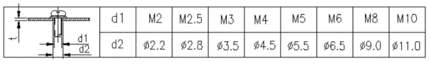
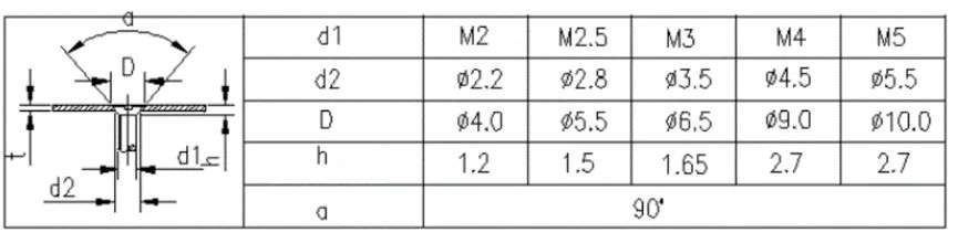
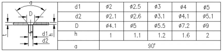
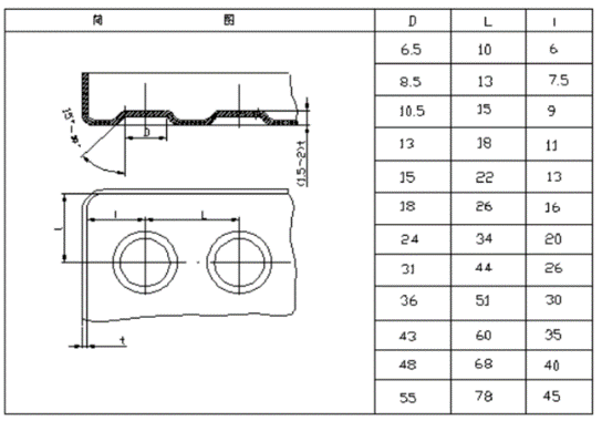
7, Through holes and countersunk holes for screws, bolts and rivets
The structural dimensions of through holes and countersunk holes for screws, bolts, and rivets are usually selected according to the corresponding tables. For countersunk holes of countersunk screws and countersunk rivets, if it is difficult to simultaneously guarantee the through hole size d2 and the countersunk hole size D due to the insufficient thickness of the sheet metal material, the through hole size d2 should be guaranteed first.
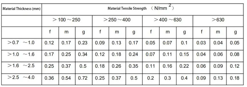
8, Limits on burrs in stamped parts and drawing design requirements
After sheet metal is stamped, burrs are formed on one side of the flat surface. To ensure the surface quality of the parts and prevent unnecessary injuries or damage, there are usually restrictions on the height of the burrs on the stamped parts, as shown in the table below. Grade f (precision grade) is suitable for parts with high requirements; grade m (medium grade) is suitable for parts with medium requirements; and grade g (rough grade) is suitable for parts with low requirements. In part design drawings, deburring is typically required for the outer surface of the parts, cable through-holes, and edges that are easily touched by hands.
II, Bending
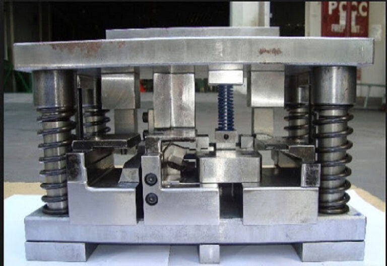
Sheet metal bending refers to the processing of changing the angle of sheet metal or sheet components, such as bending the sheet into a V-shape or U-shape. Generally, there are two methods: one is die bending, used for sheet metal structures with complex structures, small volumes, and large-volume processing; the other is bending machine bending, used for sheet metal structures with larger dimensions or lower production volumes. The following are some points to note regarding the bending process.
1, Minimum bending radius of bent parts
When sheet metal is bent, the outer layer is stretched while the inner layer is compressed in its rounded corner area. When the material thickness is constant, the smaller the inner radius (r), the more severe the stretching and compression. When the tensile stress at the outer rounded corner exceeds the material’s ultimate strength, cracks and breakage will occur. Therefore, the structural design of bent parts should avoid excessively small bending radii. The minimum bending radii for commonly used materials are shown in the table below.
| No. | Material | Minimum Bend Radius |
|---|---|---|
| 1 | 08, 08F, 10, 10F, SECC-N2, SPCC, SPTE, 0Cr18Ni9, 1Cr18Ni9, 1Cr18Ni9Ti, 1100-H24, T2 | 0.4t |
| 2 | 15, 20, Q235, Q235A, 15F | 0.5t |
| 3 | 25, 30, Q255 | 0.6t |
| 4 | 1Cr13, H62 (M, Y, Y2, cold rolled) | 0.8t |
| 5 | 45, 50 | 1.0t |
| 6 | 55, 60 | 1.5t |
| 7 | 65Mn, 60SiMn, 1Cr17Ni7, 1Cr17Ni7-Y, 1Cr17Ni7-DY, SUS301, 0Cr18Ni9, SUS302 | 2.0t |
2, Straight edge height of bent parts
1) Minimum height of a straight edge under normal circumstances
The minimum height of the straight edge of the bent part should be: h > 2t, where t is the material thickness, as shown in the figure below.
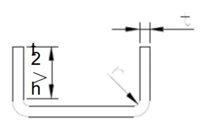
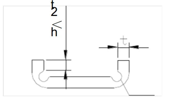
2) Machining methods for straight edge height with special requirements
If the design requires the straight edge height h≤2t of the bent part, then the bending height should be increased first, and then processed to the required size after bending; or the process groove should be processed first in the bending deformation zone before bending, as shown in the figure below.
3) Height requirements for straight edges when the side of a bent part has an angle
When the side of the bent part has an angle, the minimum height requirement of the straight edge of the side is: h = (2 ~ 4)t > 3mm.

3, The hole edge distance of bent parts generally requires
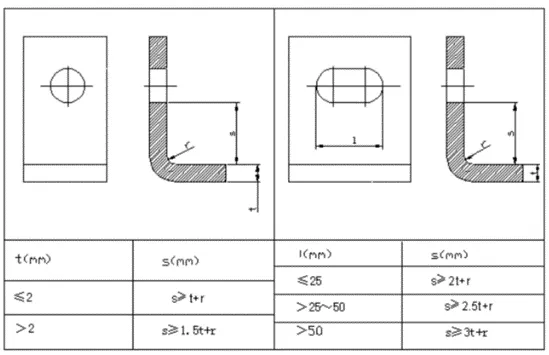
When the processing step involves punching before bending, the hole should be positioned outside the bending deformation zone to prevent deformation during bending. See the table below for the distance from the hole wall to the bending edge.
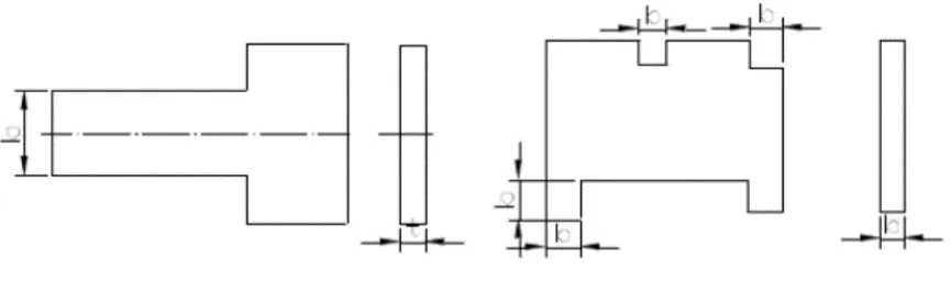
4, Process cut for partial bending
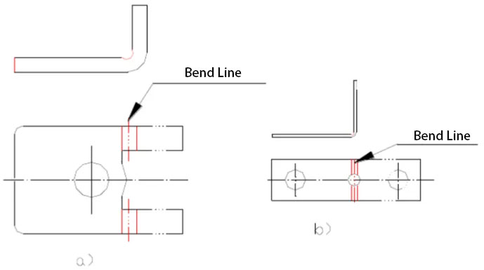
1) Design treatment method for partial bending
When bending a section of an edge locally, to prevent stress concentration at sharp corners and subsequent cracking, the bending line can be moved a certain distance to avoid abrupt dimensional changes (Figure a); or a process groove can be used (Figure b). Dimensional requirements: S≥R; groove width k≥t; groove depth L≥t+R+k/2.
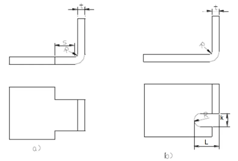
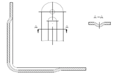
2) Cutting pattern when the hole is located within the bending deformation zone
When the hole is within the bending deformation zone, the possible cut forms are shown in the figure below.
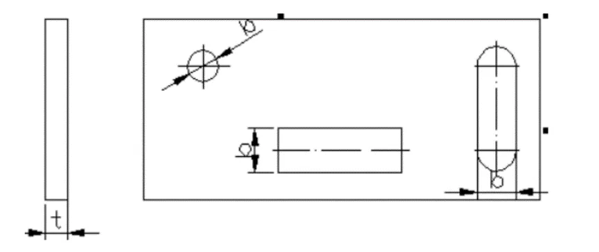
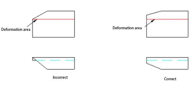
5, The beveled edge of the bend should avoid the deformation zone
For bent parts with beveled edges, the bend should avoid the bending deformation zone, as shown in the figure below.
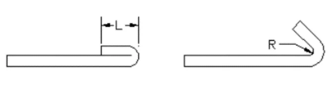
6, Width requirements for dead edges
The minimum allowable width of a dead edge (or edge with a folded edge) is related to the material thickness t and the minimum bending inner diameter R. As shown in the figure below, the minimum width of a dead edge is typically L ≥ 3.5 t + R, where t is the material thickness and R is the minimum bending inner diameter R of the preceding process.
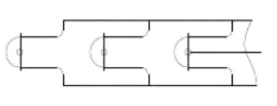
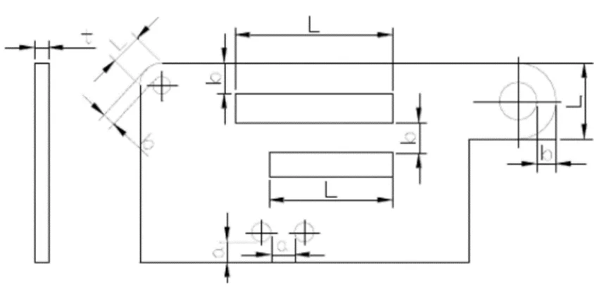
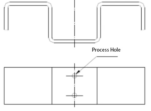
7, Added process positioning holes in the design
To ensure accurate positioning of the bending blank material in the mold and prevent scrap due to material misalignment during bending, process positioning holes are typically added in the design. This is especially important for parts that undergo multiple bending processes; the process holes must be used as the positioning reference to reduce cumulative errors and ensure product quality, as shown in the figure below.
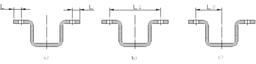
8, When designing and labeling the relevant dimensions of bent parts, the processing requirements should be considered
As shown in the figure below: a) punching the hole first and then bending it makes it easy to ensure the accuracy of dimension L and is convenient to process. b) and c) if the accuracy of dimension L is required to be high, bending is required first and then machining the hole, which is relatively more troublesome.
9, Springback of bent parts
Many factors affect the springback of bent parts, including: the mechanical properties of the material, the material thickness, the bending radius, and the normal pressure during bending.
1) Qualitative analysis of springback in bent parts
The greater the ratio of the inner corner radius of a bent part to the thickness of the sheet metal, the greater the springback.
2) Design-based methods to suppress rebound
Currently, springback in bent parts is mainly mitigated by manufacturers through specific measures in mold design. Design improvements can also reduce the springback angle. As shown in the diagram, pressing reinforcing ribs into the bending area not only increases the rigidity of the part but also helps suppress springback.
III, stretching
Deep drawing is a machining process that uses molds to stamp flat blanks of a certain shape obtained after blanking into various open hollow parts, or to reduce the diameter and increase the height of open hollow blanks. Deep drawing can be used to manufacture thin-walled parts of cylindrical, stepped, conical, spherical, box-shaped, and other irregular shapes.
Combined with other stamping forming processes such as flanging, bulging, widening, and narrowing, it can also manufacture parts with extremely complex shapes. The following are some points to note.
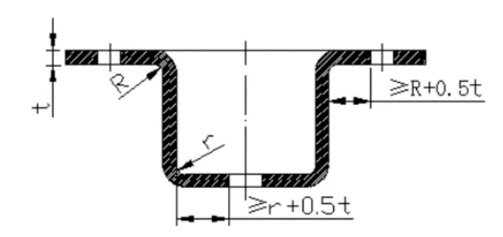
1, Requirements for the fillet radius at the bottom of the drawn part
As shown in the figure below, the fillet radius between the bottom of the stretched part and the straight wall should be greater than the material thickness t, i.e., r1 ≥ t. At the same time, in order to make the stretching process smoother, r1 is generally taken as (3~5)t, and the maximum fillet radius should be less than or equal to 8 times the material thickness, i.e., r1 ≤ 8t.
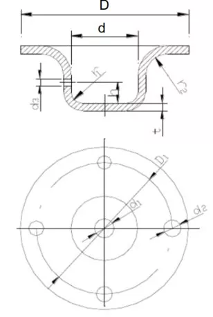
2, The fillet radius between the flange and the wall of the drawn part
As shown in the figure above, the fillet radius between the flange and the wall of the stretched part should be greater than twice the material thickness t, i.e., r2 ≥ 2t. At the same time, in order to make the stretching process smoother, r2 is generally taken as (5~10)t, and the maximum flange radius should be less than or equal to 8 times the material thickness, i.e., r2 ≤ 8t.
3, Inner diameter of a circular drawn part
The inner diameter of the circular drawn part should be D ≥ d + 10t (t is the material thickness) so that the pressure plate can press the blank material tightly during drawing to prevent wrinkling.
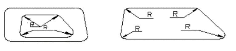
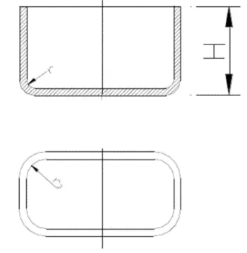
4, The fillet radius between adjacent walls of a rectangular stretched part
The fillet radius between adjacent walls of a rectangular stretching member should be r ≥ 3t. To reduce the number of stretching operations, r ≥ H/5 should be used as much as possible so that it can be stretched out in one go.
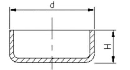
5, When forming a circular flangeless drawn part in one step, the dimensional relationship between its height and diameter is required
When a circular flangeless drawn part needs to be formed in one step, the ratio of the part height H to the diameter d should be less than or equal to 0.4, that is, H/d ≤ 0.4, as shown in the figure below.
6, Precautions for dimensioning drawn parts
1) Dimensioning requirements for tensioned parts
In the design drawings of tensioned parts, the dimensions should clearly indicate whether they must be external or internal, and cannot be both internal and external dimensions simultaneously.
2) Method for specifying dimensional tolerances for stretched parts
The inner radius of the concave and convex arcs of the drawn part and the height of the cylindrical drawn part formed in one step should be a double-sided symmetrical deviation. The deviation value is half of the absolute value of the GB IT 16 grade precision tolerance and is prefixed with ±.
IV, Forming
In addition to the cold stamping process commonly used in mechanical manufacturing, sheet metal processing also employs other special methods, such as rubber hydroforming , stretch bending , and shot peening. However, regardless of the forming process used, the following points should be noted.
1, Reinforcing ribs
Adding ribs to plate-shaped metal parts helps increase structural rigidity. Common rib structures and their dimensional relationships are shown in the table below.
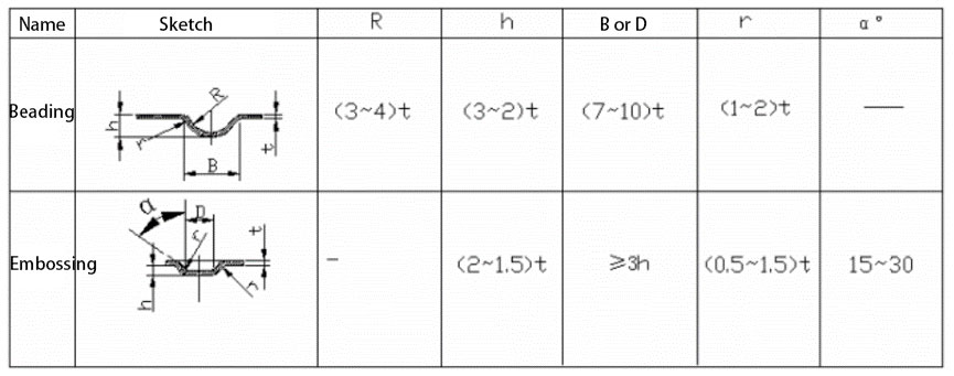
2, Minimum dimensions for convexity spacing and convexity margin
The minimum dimensions for the embossing spacing and embossing margin are typically selected from the data in the table below.
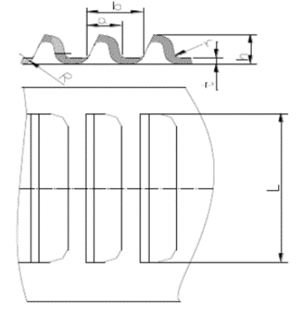
3, Venetian blinds
Venetian blinds are commonly used on the outer shell of server racks, chassis, or enclosures to provide ventilation and heat dissipation. They are formed by using one edge of a punch to cut the material, while the remaining part of the punch simultaneously stretches and deforms the material, creating an undulating shape with one side open and the other connected.
The typical structure of a venetian blind is shown in the figure below. Its dimensional design requirements are as follows: a≥4t; b≥6t; h≤5t; L≥24t; r≥0.5t. t is the material thickness.
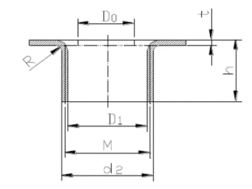
4, Hole Flanging
There are many types of hole flanges. This section mainly introduces the most common type: the internal hole flange with threaded holes, as shown in the figure below.
V, Conclusion
The structural design of sheet metal involves material manufacturing and the processing of parts or components. While meeting the functional and aesthetic requirements of the product, the structural design of sheet metal products should ensure simple stamping processes, easy fabrication of stamping molds, high sheet metal stamping quality, and dimensional stability.