1, Electrospark machining
1) Basic principles
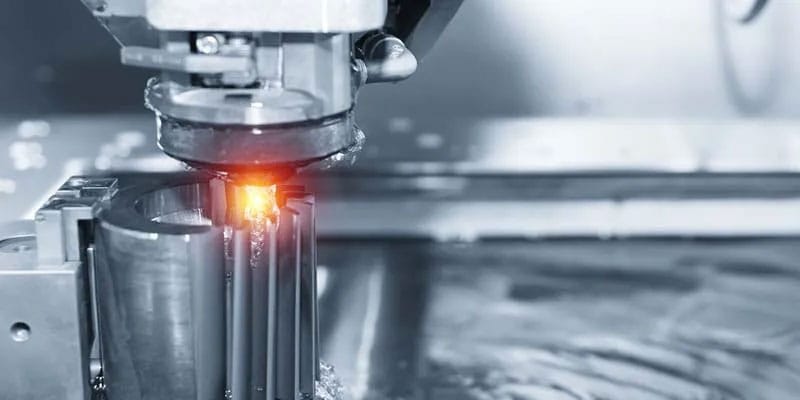
Electrospark machining is a special machining method that uses the electro-erosion effect generated by pulse discharge between two electrodes immersed in a working fluid to erode conductive materials. It is also called electrical discharge machining or electro-erosion machining. In English, it is called Electrical Discharge Machining, or EDM for short.
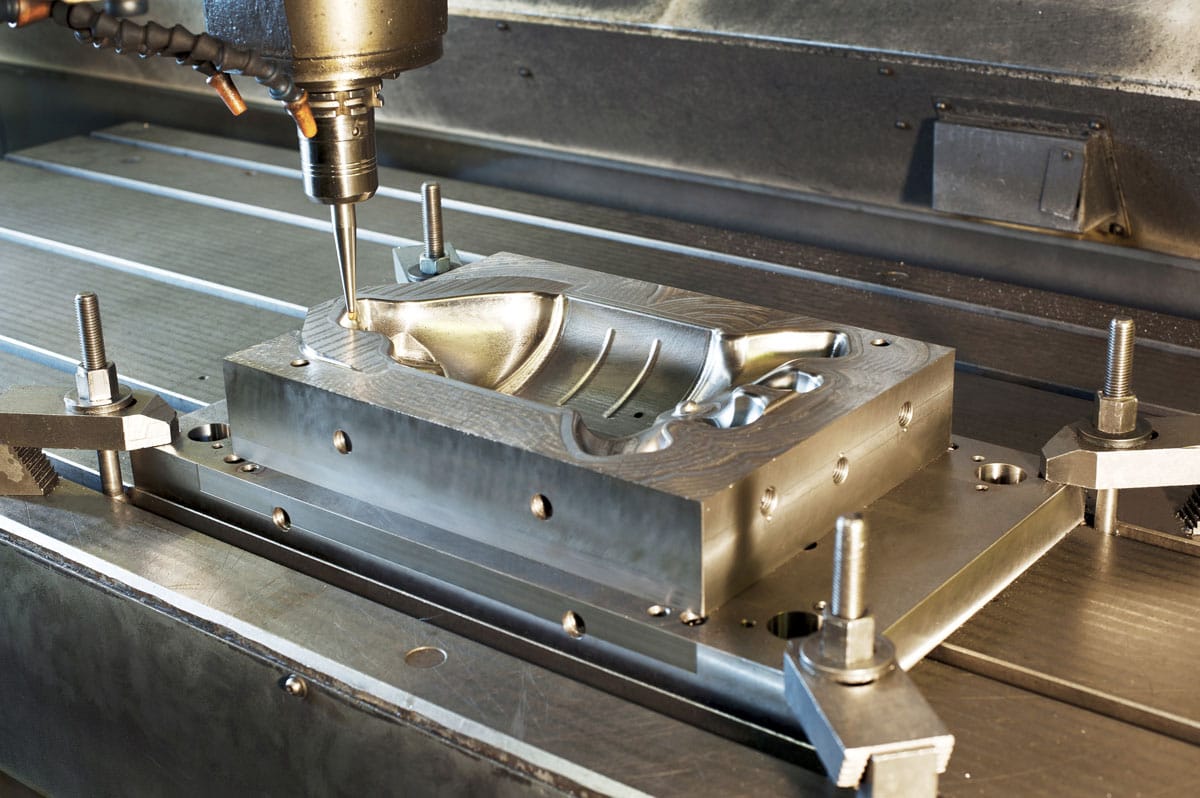
EDM is suitable for machining complex components such as small, precise cavities, narrow slots, grooves, and corners. When complex surfaces are difficult to reach, deep cuts are required, and areas with particularly high aspect ratios, EDM is superior to milling. For machining high-tech parts, re-discharging the milling electrode can improve the success rate, making EDM a more suitable option compared to the high cost of tooling.
In addition, where EDM finishing is required, EDM is used to create a spark pattern surface. With the rapid development of high-speed milling, the development space for EDM has been squeezed to a certain extent. At the same time, high-speed milling has also brought greater technological advancements to EDM. For example, the use of high-speed milling to manufacture electrodes significantly reduces the number of electrode designs due to the ability to machine confined areas and produce high-quality surface finishes. Furthermore, using high-speed milling to manufacture electrodes can elevate production efficiency to a new level and ensure high electrode precision, thereby improving the accuracy of EDM.
If most of the cavity processing is done by high-speed milling, EDM is only used as an auxiliary means to clean corners and trim edges, so that the allowance is more uniform and less.
2) Basic equipment: Electric discharge machining machine.
3) Main features:
It can process materials that are difficult to cut with ordinary cutting methods and workpieces with complex shapes; there is no cutting force during processing; no defects such as burrs and tool marks and grooves are generated; the tool electrode material does not need to be harder than the workpiece material; electric energy is directly used for processing, which facilitates automation; a metamorphic layer is generated on the surface after processing, which must be further removed in some applications; the purification of the working fluid and the treatment of smoke pollution generated during processing are relatively troublesome.
EDM has the following characteristics:
It can process any high-strength, high-hardness, high-toughness, high-brittleness and high-purity conductive materials; there is no obvious mechanical force during processing, and it is suitable for processing low-rigidity workpieces and microstructures: the pulse parameters can be adjusted as needed, and rough processing, semi-finishing and finishing can be performed on the same machine tool; the pits on the surface after EDM are conducive to oil storage and noise reduction; the production efficiency is lower than that of cutting processing; part of the energy in the discharge process is consumed on the tool electrode, resulting in electrode loss and affecting the forming accuracy.
(4) Scope of use
Processing molds and parts with complex-shaped holes and cavities; processing various hard and brittle materials such as cemented carbide and hardened steel; processing deep and fine holes, special-shaped holes, deep grooves, narrow slits and cutting thin slices; processing various forming tools, templates, thread ring gauges and other tools and measuring instruments.
EDM must have three conditions:
- Pulse power supply must be used
- An automatic feed adjustment device must be used to maintain a small discharge gap between the tool electrode and the workpiece electrode
- Spark discharge must be carried out in a liquid medium with a certain dielectric strength (10~107Ω·m).
Not all mold steels can be processed by mirror EDM
Some mold steels can easily achieve a mirror finish with EDM, while others simply cannot. Furthermore, the harder the mold steel, the better the EDM finish. Please refer to the table below for various materials and mirror finish properties.
| category | Material Name | Mirror performance |
| A | SKD61STAVAX (S136)PD555NAK80718H | very goodvery goodvery goodvery goodvery good |
| B | SKS3SKH9HPM38S55CH13XW10 | goodgoodgoodgoodgoodslightly worse |
| C | SKD11NAK55HPM1DH2F | DifferenceDifferenceDifferenceDifference |
| D | BsAlsuper carbide | Pear skin noodlesPear skin noodles |
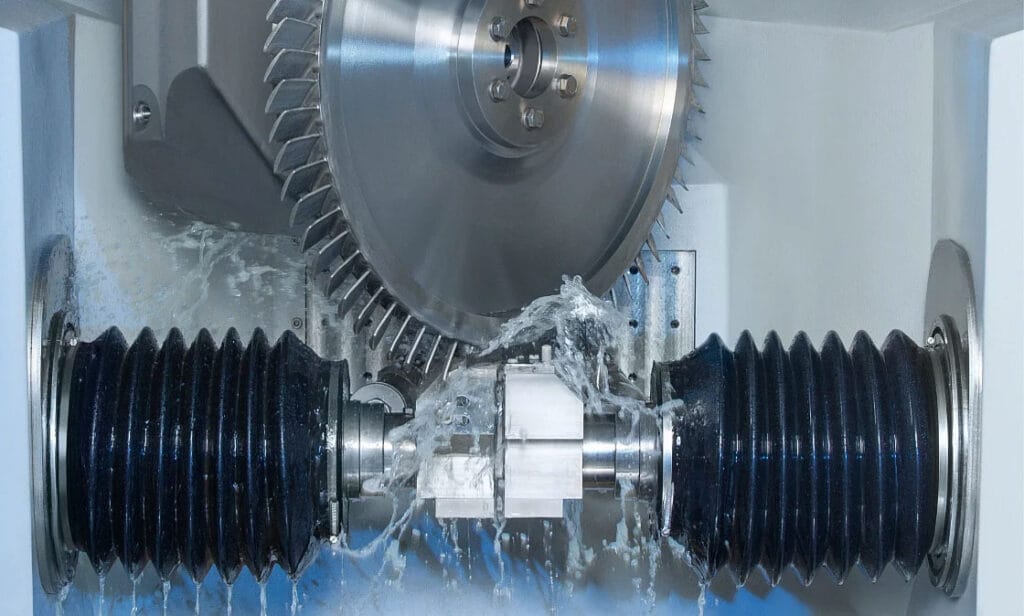
2, Wire EDM
(1) Basic principles
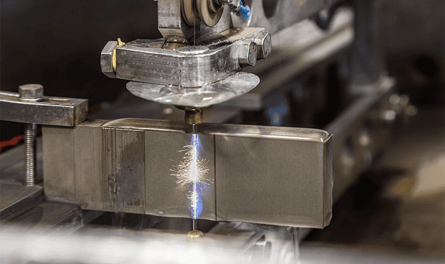
Wire Cut Electrical Discharge Machining (WEDM), also known as wire cutting, uses a continuously moving thin metal wire (called a wire electrode) as an electrode to erode metal and cut the workpiece into shape.
(2) Basic equipment: wire-cut electric discharge machine.
(3) Main features:
In addition to the basic characteristics of EDM, wire EDM also has some other characteristics:
① It is possible to process any two-dimensional surface with a straight line as the generatrix without the need to manufacture tool electrodes with complex shapes;
②Can cut narrow slits of about 0.05 mm;
③During the processing, all the excess materials are not processed into waste chips, which improves the utilization rate of energy and materials;
④ In low-speed wire EDM where the electrode wire is not recycled, the continuous renewal of the electrode wire is beneficial to improving machining accuracy and reducing surface roughness;
⑤ The cutting efficiency that can be achieved by wire-cutting electric discharge is generally 20-60 mm2/min, and can reach up to 300 mm2/min; the processing accuracy is generally ±0.01 to ±0.02 mm, and can reach up to ±0.004 mm; the surface roughness is generally Ra2.5 to 1.25 microns, and can reach up to Ra0.63 microns; the cutting thickness is generally 40-60 mm, and the thickest can reach 600 mm.
(4) Scope of use
They are primarily used for machining various complex and precise workpieces, such as punches, dies, retaining plates, and stripper plates for blanking dies; forming tools, templates, and metal electrodes for EDM; and various micro-holes, narrow slots, and arbitrary curves. With outstanding advantages such as small machining allowances, high machining precision, short production cycles, and low manufacturing costs, wire EDM machines have found widespread application in production. Currently, wire EDM machines account for over 60% of all EDM machine tools, both domestically and internationally.
Wire EDM is a technology that can achieve workpiece size processing. Under certain equipment conditions, the rational formulation of the processing route is an important link to ensure the quality of workpiece processing.
The process of wire EDM machining molds or parts can generally be divided into the following steps.
Analyze and review drawings
Analyzing the drawings is the first step that is crucial to ensuring the workpiece processing quality and comprehensive technical indicators. Taking the blanking die as an example, when digesting the drawings, the first thing to do is to pick out the workpiece drawings that cannot or are not easy to be processed by wire EDM. There are roughly the following types:
- Workpieces with very high requirements for surface roughness and dimensional accuracy, which cannot be manually ground after cutting;
- The workpiece with a narrow gap smaller than the diameter of the electrode wire plus the discharge gap, or the workpiece with a rounded corner formed by the discharge gap of the electrode dead plate derrick is not allowed at the corner of the pattern;
- Non-conductive materials;
- Parts whose thickness exceeds the span of the wire rack;
- The processing length exceeds the effective travel length of the x, y slide and the workpiece requires higher precision.
Under the conditions of conforming to the wire cutting process, attention should be paid to careful consideration of surface roughness, dimensional accuracy, workpiece thickness, workpiece material, size, fit clearance and thickness of stamped parts.
Programming Notes:
- Determination of die clearance and transition circle radius:
Reasonably determine the die gap. The reasonable selection of the die gap is one of the key factors related to the life of the die and the size of the burrs on the punched parts. The die gap of different materials is generally selected in the following range:
For soft blanking materials, such as copper, soft aluminum, semi-durable aluminum, bakelite, red cardboard, mica sheets, etc., the gap between the male and female dies can be selected to be 10%-15% of the thickness of the blanking material.
For hard blanking materials, such as iron sheets, steel sheets, silicon steel sheets, etc., the gap between the male and female dies can be selected to be 15%-20% of the blanking thickness.
This is actual empirical data from wire EDM punching dies, which are slightly smaller than the internationally popular large-gap dies. This is because the workpiece surface during wire EDM has a brittle, melted layer. Higher machining parameters result in poorer surface roughness and a thicker melted layer. As the die is punched more frequently, this brittle surface layer gradually wears away, causing the die gap to widen.
Reasonably determine the transition radius. To extend the service life of general cold stamping dies, a transition radius should be added to lines, lines, and intersections, especially at shallow corners. The size of the transition radius can be determined based on the thickness of the material being punched, the shape of the die, the required lifespan, and the technical requirements of the part being punched. As the thickness of the part increases, the transition radius can be increased accordingly. Generally, the radius should be within the range of 0.1-0.5 mm.
For parts with thinner materials, smaller mold clearance, and where the transition circle cannot be enlarged, a transition circle is generally added at the corners of the pattern in order to obtain a good clearance between the male and female dies. This is because the electrode wire machining trajectory will naturally form a transition circle at the inner corner with a radius equal to the electrode wire radius plus the single-sided discharge gap.
- Calculate and write machining programs
When programming, you should choose a reasonable clamping position according to the material situation, and determine a reasonable starting point and cutting route.
The starting point of cutting should be at the corner of the figure, or at a place where the convex point can be easily trimmed off.
The cutting route is mainly based on the principle of preventing or reducing mold deformation. Generally, it is easier to cut the graphics close to the clamping side last.
- Program tape and proofreading tape for threading
After creating the paper tape according to the program sheet, the program sheet and the prepared paper tape must be proofread individually. Only after entering the program into the controller using the proofread paper tape can a trial cut be made. Simple workpieces that are reliable can be processed directly. For molds with high dimensional accuracy requirements and small clearances between the male and female dies, trial cuts must be made with thin stock. The accuracy and clearances can be checked on the cut piece. If any discrepancies are found, timely analysis should be conducted to identify the problem, and the program should be modified until it passes muster before the mold can be officially processed. This step is crucial to preventing scrapped workpieces.
Depending on the actual situation, the program can also be input directly from the keyboard, or directly transferred from the programming machine to the controller.
3, Electrochemical Machining
(1) Basic principles
Electrolytic machining is a process that uses the principle of anodic dissolution in the electrolytic process and the aid of a formed cathode to shape the workpiece into a certain shape and size.
(2) Scope of use
Electrochemical machining (ECM) offers significant advantages for machining difficult-to-machine materials, complex shapes, or thin-walled parts. It has gained widespread application, such as in the rifling of gun barrels, blades, integral impellers, molds, special-shaped holes and parts, chamfering, and deburring. In the machining of many parts, the ECM process has become an important, even irreplaceable, position.
(3) Advantages
Wide processing range. Electrolytic machining can process almost all conductive materials and is not limited by the material’s mechanical and physical properties such as strength, hardness, and toughness. The metallographic structure of the material remains essentially unchanged after processing. It is commonly used to process difficult-to-machine materials such as cemented carbide, high-temperature alloys, hardened steel, and stainless steel.
(4) Limitations
The processing accuracy and processing stability are not high; the processing cost is high, and the smaller the batch, the higher the additional cost per piece.
4, Laser processing
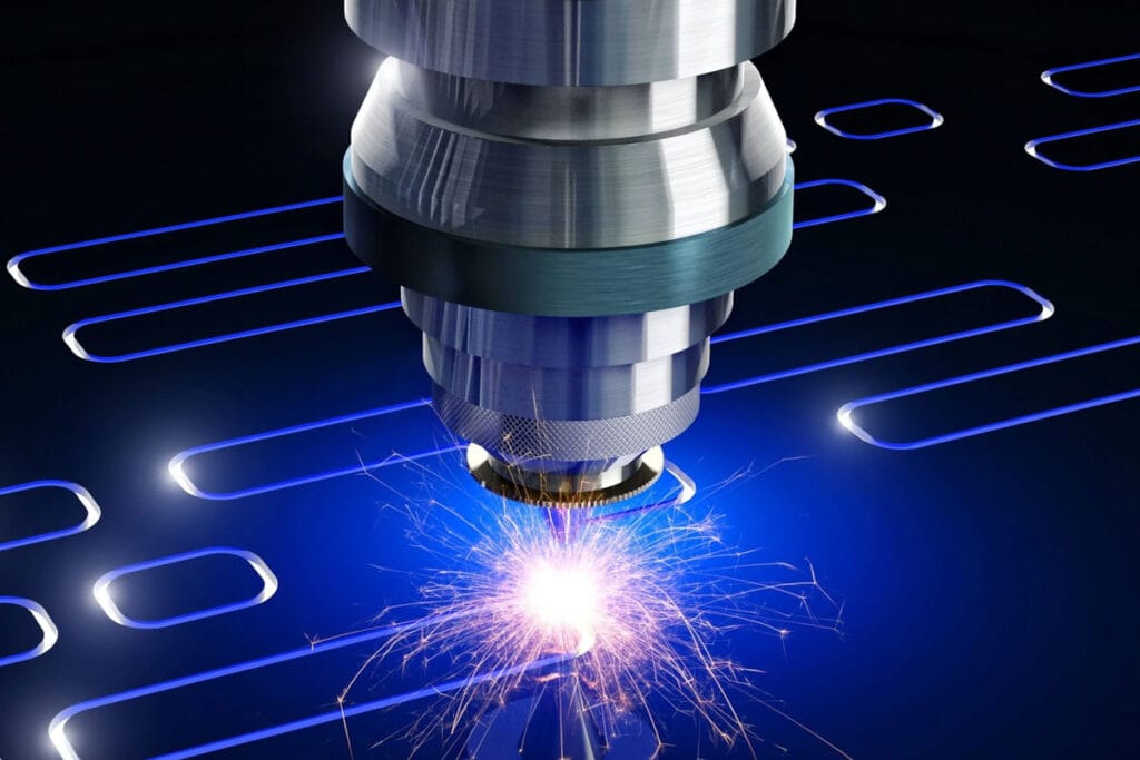
(1) Basic principles
Laser processing uses the energy of light to reach a very high energy density at the focal point after being focused by a lens, so that the material is melted or vaporized in a very short time and etched away to achieve processing.
(2) Main features
Laser processing technology offers advantages such as minimal material waste, significant cost-effectiveness in large-scale production, and strong adaptability to the processing object. In Europe, laser technology is primarily used for welding specialized materials such as high-end automobile bodies and chassis, aircraft wings, and spacecraft fuselages.
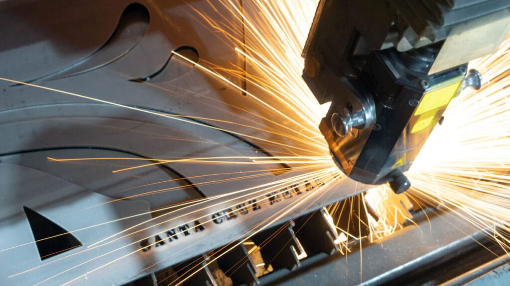
(3) Scope of use
Laser processing is the most common application of laser systems. Its main technologies include: laser welding, laser cutting, surface modification, laser marking, laser drilling, micromachining and photochemical deposition, stereolithography, laser etching, etc.
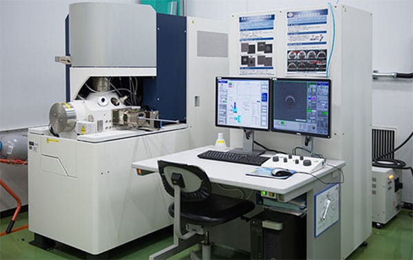
5, Electron beam processing
(1) Basic principles
Electron beam processing is the process of processing materials using the thermal or ionizing effects of a high-energy convergent electron beam.
(2) Main features
High energy density, strong penetration ability, wide range of one-time penetration depth, large weld width ratio, fast welding speed, small heat-affected zone and small working deformation.
(3) Scope of use
Electron beam machining can process a wide range of materials and extremely small areas. It can achieve nanometer-level precision, enabling molecular and atomic processing. It also boasts high productivity and minimal pollution, though equipment costs are high. It can process micropores and narrow slits, and can also be used for welding and fine photolithography. Vacuum electron beam welding of axle housings is a major application of electron beam machining in the automotive industry.
6, Ion Beam Machining
(1) Basic principles
Ion beam processing is a process in which the ion flow generated by an ion source is accelerated and focused onto the surface of the workpiece under vacuum conditions to achieve processing.
(2) Main features
Because the ion flux density and ion energy can be precisely controlled, the processing effect can be precisely controlled, achieving ultra-precision processing at the nanoscale, even the molecular and atomic levels. Ion beam processing produces little pollution, minimal processing stress and deformation, and is highly adaptable to the material being processed, but the processing cost is high.
(3) Scope of use
Ion beam processing can be divided into two types according to its purpose: etching and coating.
1) Etching
Ion etching is used to create grooves in gyroscope air bearings and dynamic pressure motors, offering high resolution, precision, and repeatability. Another application of ion beam etching is etching high-precision patterns for electronic components such as integrated circuits, optoelectronic devices, and optical integrated circuits. Ion beam etching is also used to thin materials and create specimens for transmission electron microscopy.
2) Ion beam coating processing
Ion beam coating processes include sputtering deposition and ion plating. Ion plating can coat a wide range of materials, including metal or non-metallic surfaces, and can deposit metal or non-metallic thin films on various alloys, compounds, certain synthetic materials, semiconductor materials, and high-melting-point materials.
Ion beam coating technology can be used to coat lubricating films, heat-resistant films, wear-resistant films, decorative films and electrical films, etc.
7, Plasma arc processing
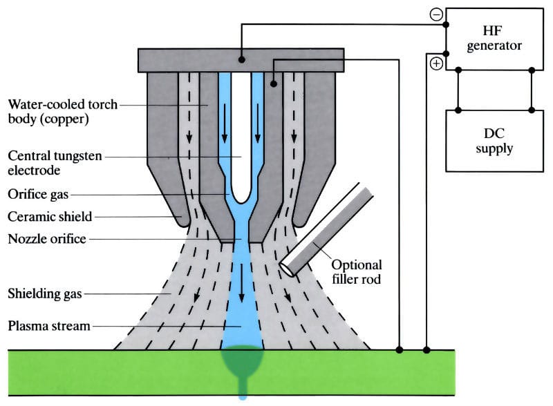
(1) Basic principles
Plasma arc processing is a special processing method that uses the thermal energy of a plasma arc to cut, weld, and spray metals or non-metals.
(2) Main features
1) Micro plasma arc welding can weld foils and thin plates;
2) It has a small hole effect and can better achieve single-sided welding and double-sided free forming;
3) The plasma arc has high energy density, high arc column temperature, strong penetration ability, and can weld through and form both sides of 10-12mm thick steel without beveling. It has fast welding speed, high productivity and low stress and deformation.
4) The equipment is relatively complex and consumes a lot of gas, so it is only suitable for indoor welding.
(3) Scope of use
It is widely used in industrial production, especially in the welding of copper and copper alloys, titanium and titanium alloys, alloy steel, stainless steel, molybdenum and other metals used in military and cutting-edge industrial technologies such as aerospace, such as titanium alloy missile casings and some thin-walled containers on aircraft.
8, Ultrasonic machining
(1) Basic principles
Ultrasonic machining (USM) is a specialized process that uses a small-amplitude ultrasonic vibration tool to gradually break down the workpiece surface through the hammering action of abrasive particles suspended in a liquid between the tool and the workpiece. It is commonly used for perforating, cutting, welding, trepanning, and polishing.
(2) Main features
It can process any material and is particularly suitable for processing various hard, brittle and non-conductive materials. It has high processing precision and good surface quality for workpieces, but its productivity is low.
(3) Scope of use
Ultrasonic machining is mainly used for drilling (including round holes, special-shaped holes and curved holes), cutting, grooving, nesting, engraving, deburring of batch small parts, polishing of mold surfaces and dressing of grinding wheels of various hard and brittle materials such as glass, quartz, ceramics, silicon, germanium, ferrite, gemstones and jade.
9, Chemical processing
(1) Basic principles
Chemical Etching is a special processing method that uses acid, alkali or salt solution to corrode and dissolve the workpiece material to obtain the workpiece with the desired shape, size or surface state.
(2) Main features
1) It can process any metal material without being restricted by hardness, strength and other properties;
2) Suitable for large-area processing and can process multiple pieces at the same time;
3) No stress, cracks or burrs are generated, and the surface roughness reaches Ra1.25-2.5μm;
4) Easy to operate;
5) Not suitable for processing narrow slots and holes;
6) It is not advisable to eliminate surface defects such as unevenness and scratches.
(3) Scope of use
Suitable for large-area thickness reduction processing; suitable for processing complex holes on thin-walled parts.