How does primary injection work?
When using one-stage injection molding in plastics, high pressure and high speed injection can quickly fill the mold cavity, but the product is prone to overflow and burning, and it is difficult to find the switching point from pressure maintenance to holding pressure. Low pressure and low speed injection require very high mold temperature, and the product may solidify when exposed to cold, resulting in short shots. Therefore, one-stage injection is rarely used in plastics molding, generally only for products with simple structures and low dimensional precision requirements.
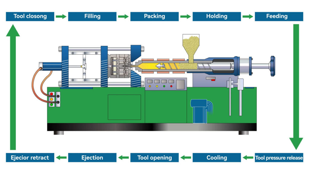
Working principle of multi-stage injection
For parts with high dimensional accuracy, complex structure, high brightness appearance and large parts, multi-stage injection is used, which combines the advantages of high pressure and high speed of single-stage injection and low pressure and low speed.
Multi-stage injection refers to removing the holding time and pressure from the debugging parameters. When the screw fills the melt into the cavity, after each screw position is increased, the changes from small to large in the product, the material trend and process defects are observed, and different pressures and speeds are used to control it at each position. Finally, the injection position and the holding pressure position of each section are determined.
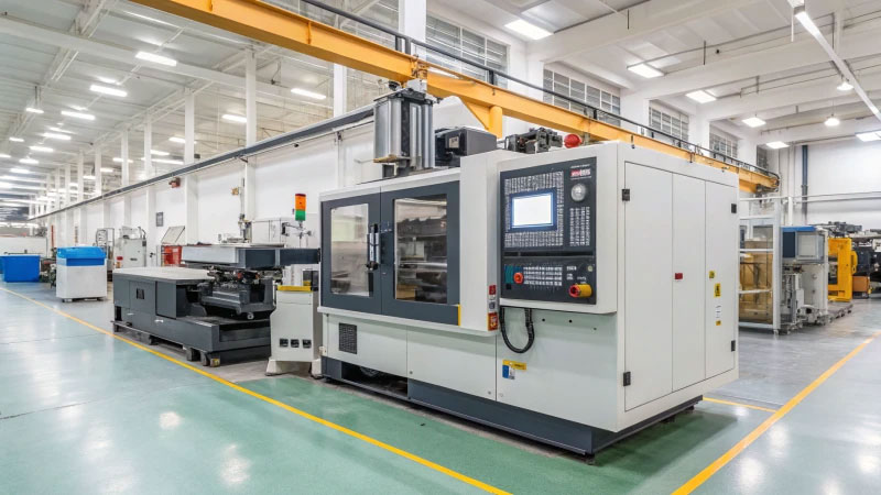
Multi-stage injection process conditions
①Set the injection position according to the shape, size and quantity of the product.
② Setting the flow resistance of melt filling the mold─injection pressure.
③Set the fluidity of the material used-injection speed.
Multi-stage injection segment setting
In principle, multi-stage injection molding requires at least four injection stages, with each stage using different pressure and speed. The controlled areas also differ (Figure 1). Using multi-stage injection not only effectively protects the mold but also facilitates secondary debugging if defects occur in the product.
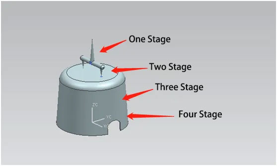
The first section of the gate area adopts medium pressure and low speed;
The second gate area uses medium pressure and medium speed;
The third main area (filled to 90% of the entire product) uses high pressure and high speed;
The final stage uses low pressure and low speed.
Multi-stage injection planning
Multi-stage injection uses multi-stage injection with different functions in different mold structures, different product shapes, product quality, material shrinkage fluidity and product defects. The following table is an injection plan based on actual work experience.
| Workmanship defects | Injection pressure | Injection speed |
| Materials with good fluidity | Low pressure → Medium pressure → High pressure → Low pressure | Low speed → Medium speed → High speed → Low speed |
| Materials with poor flowability | Medium pressure → Medium pressure → High pressure → Low pressure | Medium speed→medium speed→high speed→medium speed |
| Prevent overflow | Low pressure → Medium pressure → High pressure → Low pressure | Low speed → low speed → medium speed → low speed |
| Prevent short injection | Medium pressure → Medium pressure → High pressure → High pressure | Medium speed→medium speed→high speed→medium speed |
| Prevent burning | Low speed → Medium speed → Medium speed → Low speed | |
| Prevent dents | Medium pressure → high pressure → high pressure → low pressure | Medium speed → high speed → medium speed → low speed |
| Prevent jet marks | Low speed → low speed → medium speed → low speed | |
| Improve weld line strength | Low speed → low speed → high speed → medium speed | |
| Improve transparency | Medium pressure → Medium pressure → High pressure → Low pressure | Medium speed→High speed→High speed→Medium speed |
| Reduce silver streaks | Low speed → Low speed → Medium speed → Medium speed |
Note: Multi-stage injection plans with different functions
Multi-stage injection precautions
1. The end point position on the monitoring screen is different from the actual position. When the screw stops injecting, it will move forward due to inertia. The end point position on the monitoring screen shall prevail.
2. Each shutdown/startup requires injection molding – material reduction – pressure reduction to prevent the mold temperature (melt temperature) from cooling down when the melt fills the cavity, blocking the sprue and runner and causing material plugging.
3. Too many injection sections are set during molding, resulting in insufficient fluidity of the melt, which results in the cavity not being filled within the set injection time, causing product deformation, under-injection and shrinkage.
4. For hot runner injection molds, since there is no gate or the structure is simple, three-stage injection can be set to meet the molding requirements.
5. The transfer pressure holding method usually uses position pressure holding and time pressure holding. When the raw material flow is good and the molding is stable, the transfer pressure holding method adopts position pressure holding; on the contrary, when the material flow is poor, the equipment is seriously aged, and the injection process is unstable, the transfer pressure holding method adopts time pressure holding.
6. After the product process is debugged, it is necessary to track the production to prevent process defects such as shrinkage, burning, and gas marks on the product due to changes in mold temperature and material temperature.


