Introduction
If designers want to make good use of CNC processing, they have to design according to the processing rules, but there is no unified standard in this industry, which is indeed troublesome.
This article discusses best practices for designing parts for modern CNC systems (without considering cost). If you’re looking for tips on cost-effective CNC part design, please refer to other articles.
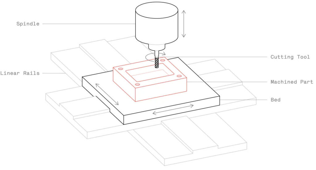
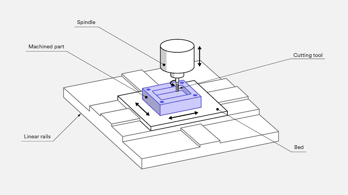
Simply put, CNC machining is “subtractive work”: using a high-speed rotating tool to cut down from a whole piece of material to make parts according to the model. Both metal and plastic can be processed.
CNC-machined parts are precise in size and tolerance, making them suitable for both mass production and single-piece machining. In fact, using CNC for metal prototyping is now quite cost-effective, even compared to 3D printing.
What are the limitations of CNC design?
CNC machining design is quite flexible, but it also has limitations, mainly related to the shape of the tool and the areas it can reach.
The most commonly used CNC tools (end mills, drills) are cylindrical and have a limited cutting length.
As they cut material, the tool’s shape is “imprinted” on the part. For example, no matter how small the tool, the internal corners of a part will always have a curvature, not a sharp corner.
The tool must be positioned directly above the workpiece to cut, so any areas it can’t reach can’t be machined. The only exception is the “bite edge,” which we’ll discuss later.
It’s best to design a part so that all features (holes, grooves, vertical walls, etc.) align with one of the six cardinal directions (front, back, left, right, up, and down). This is just a suggestion, not a hard and fast rule, as 5-axis CNC machines offer greater flexibility in how they hold the workpiece.
Furthermore, deep, narrow areas on parts present challenges. For example, milling the bottom of a deep groove requires a long-axis tool, which reduces tool rigidity, makes it prone to vibration, and compromises accuracy.
Therefore, experts recommend designing parts so that they can be machined with a tool of the largest diameter and shortest length possible.
CNC design considerations
The trouble with designing parts for CNC machining is that there are no unified industry standards – machine tools and cutting tools are constantly being upgraded, and the range of processing capabilities is also expanding.
Here are some suggested sizes and practical achievable ranges for common features.
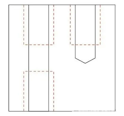
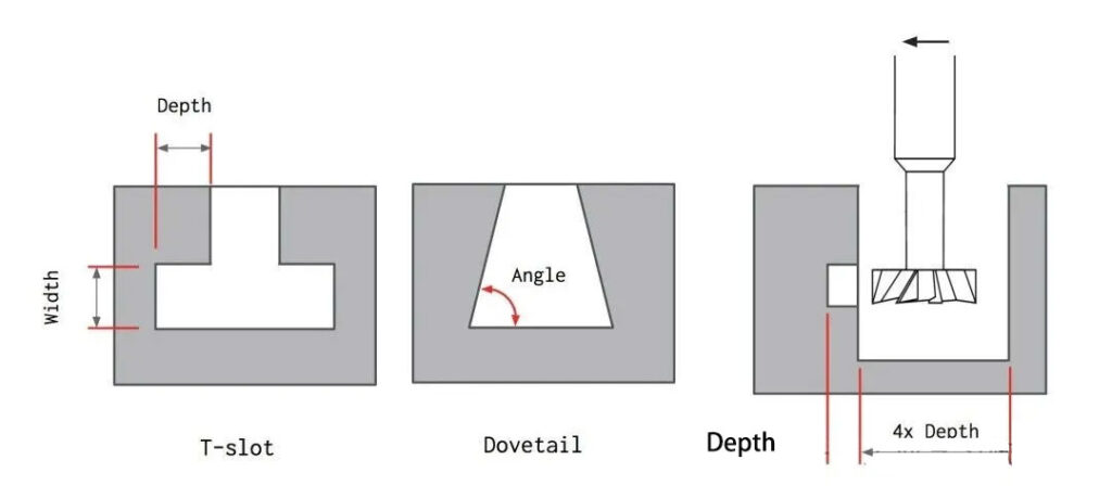
1.Grooves and cavities
The recommended depth is four times the width.
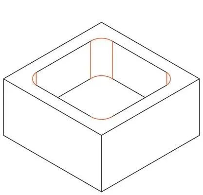
The cutting length of an end mill is generally three to four times its diameter. If the depth-to-width ratio is too large, the tool will easily warp, chip removal will be difficult, and it will vibrate.
Keeping the groove depth within four times the width will yield better results.
If a deeper cavity is required, consider designing the part with different depths (see the figure above for a specific example).
A word about deep cavity milling:
A cavity is considered deep if its depth exceeds six times the tool diameter. Using specialized tools, the tool diameter to cavity depth ratio can be as low as 1:30 (for example, a 1-inch diameter end mill can mill up to 30 cm deep).
2.The radius of the vertical corner of the inner edge:
It is recommended to be at least 1/3 of the cavity depth (or larger).
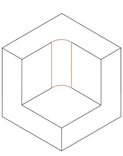
Designing to the recommended internal corner radius ensures the use of the appropriate tool diameter and adheres to the aforementioned cavity depth specifications. Increasing the corner radius slightly (for example, by 1 mm) allows the tool to follow a circular arc rather than a 90° angle—a better approach, resulting in a smoother surface finish. If a sharp 90° corner is absolutely necessary, avoid reducing the corner radius; instead, add a T-shaped undercut.
Bottom plate radius:
0.5 mm, 1 mm, or no radius at all is recommended;
in fact, other radii can also be made.
The blade of an end mill is either flat or slightly curved. If you want to make other base plate radii, you can use a ball-nose cutter. It is a good idea to design according to the recommended values, which will also make the machining process easier for the technician.
3.Minimum wall thickness for thin walls:
Recommended: 0.8 mm for metal parts, 1.5 mm for plastic parts;
Practical achievable: 0.5 mm for metal parts, 1.0 mm for plastic parts.
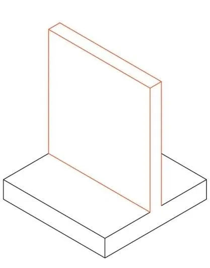
If the wall thickness is too thin, the material’s rigidity will decrease, causing vibration during machining and compromising precision. Plastic parts are even more problematic, as they are prone to warping due to internal stress and can be softened by the heat of machining. Therefore, it is best to leave a larger minimum wall thickness for plastic parts.
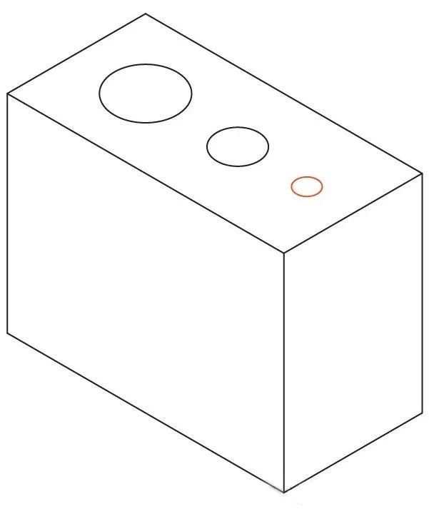
4.Hole
diameter:
Standard drill bit size is recommended;
diameters larger than 1 mm can be processed.
Holes can be made with a drill or end mill. Drill bit sizes are standardized (both metric and imperial). If the hole tolerances are tight, a reamer or boring tool is used for finishing. For holes less than 20 mm in diameter, a standard-sized drill is recommended.
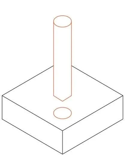
Maximum depth of the hole:
recommended is 4 times the diameter;
generally 10 times can be achieved;
in special cases, 40 times can also be processed.
Holes with non-standard diameters must be machined with an end mill. In this case, the maximum cavity depth limit mentioned above must be adhered to and the design should be based on the recommended maximum depth. For holes deeper than typical, a specialized drill (minimum diameter 3 mm) is required. Blind holes machined with a drill have a 135° taper at the bottom, while holes machined with an end mill have a flat bottom. In CNC machining, there’s no preference between through holes and blind holes; both can be produced.
5.Thread
size:
Minimum M2;
M6 or larger is recommended.
Internal threads are processed with taps, and external threads are processed with dies. Taps and dies can process threads up to M2.
CNC thread cutters are very common and are preferred by machine operators because they reduce the risk of the tap breaking. These cutters are typically used for threads M6 and above.
Thread length:
The shortest is 1.5 times the diameter;
3 times the diameter is recommended.
The force on the thread is mainly borne by the first few teeth (up to 1.5 times the diameter), so the thread length does not need to exceed 3 times the diameter.
When using a tap to process threads in a blind hole (that is, all threads smaller than M6), a section of unthreaded part should be left at the bottom of the hole, the length of which is equal to 1.5 times the diameter.
If a CNC thread cutter can be used (i.e. the thread is larger than M6), the hole can be threaded from beginning to end.
6.Minimum hole
Minimum hole diameter for small features :
2.5 mm (0.1 in) is recommended;
0.05 mm (0.005 in) is also possible.
Most machine shops can accurately machine small grooves and holes using tools smaller than 2.5 mm (0.1 in).
Most machine shops can accurately machine small grooves and holes using tools smaller than 2.5 mm (0.1 in).
Anything smaller than this is considered micromachining. Machining such small features (where the physical processes of cutting differ) requires specialized tools (such as micro drills) and specialized skills, so it should be avoided unless absolutely necessary.
7.Tolerance
Standard tolerance: ±0.125 mm (0.005 inches)
Generally achievable: ±0.025 mm (0.001 inches)
Special cases: ±0.0125 mm (0.0005 inches) can also be achieved
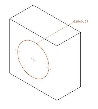
Tolerance is the allowable error in a part’s dimensions. The precise tolerances achieved depend on the size and shape of the part, but the values listed above are for reference only. If tolerances aren’t specified, most machine shops will adhere to a standard ±0.125 mm (0.005 in).
8.Font size for text and lettering
The recommended font size for text and lettering is 20 points or above, and the lettering depth is 5 mm.
Engraved text is preferred to embossed text because less material is removed. A sans-serif font (such as Arial or Verdana) at least 20 points is recommended. Many CNC machines have pre-programmed routines for these fonts.
Machine setup and part orientation
The schematic diagram of parts that need to be set multiple times is as follows:
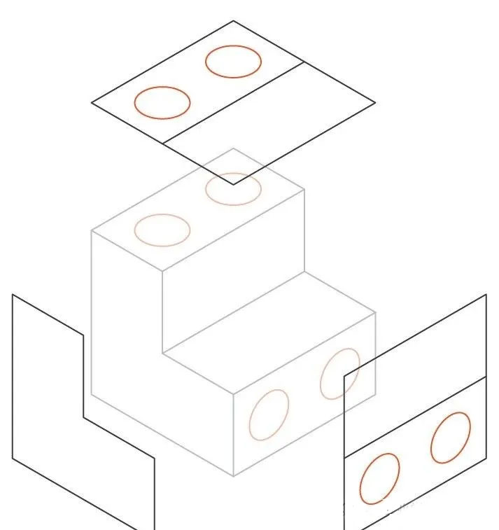
As mentioned earlier, a major limitation of CNC design is the tool’s ability to reach the desired area. To machine all surfaces of a part, the workpiece often has to be flipped multiple times.
For example, the part in the picture above has to be flipped three times in total: twice to process the holes along the two main directions, and a third time to process the back of the part.
Every time the workpiece is flipped, the machine must be recalibrated and a new coordinate system must be set.
The number of clamping times of the machine must be considered during design for two reasons:
First, the number of clamping times will affect the cost;
Secondly, flipping and realigning parts manually increases the total processing time. Generally speaking, flipping a part 3-4 times is acceptable, but more than that is unnecessary.
If you want the highest possible accuracy in the relative positioning of two features, you must machine them in the same setup, because each re-setup introduces a small (but significant) error.
Five-axis CNC machining
If you use five-axis CNC machining, you don’t need multiple clamping. Multi-axis CNC can process parts with complex shapes because it has two more rotation axes.
Five-axis CNC allows the tool to always stick to the surface to be cut, and can also take more complex and efficient tool paths, so that the part surface is smoother and the processing time is shorter.
Of course, five-axis CNC machines have their limitations. The limitations on basic tool shapes and inaccessible areas remain (for example, parts with complex internal shapes still can’t be machined). Furthermore, using this type of equipment is more expensive.
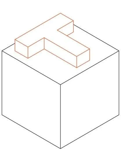
Design undercut
Undercuts are features that cannot be machined with standard cutting tools because the surface is inaccessible from directly above.
There are two main types of undercuts: T-slots and dovetail slots. Undercuts can be single-sided or double-sided and require specialized tools.
A T-slot tool is essentially a horizontal cutting insert mounted on a vertical axis. Undercut widths typically range from 3 mm to 40 mm. It’s recommended to use standard widths (such as whole millimeters or standard fractions of an inch) because this makes it easier to find readily available tools.
The angle of the dovetail tool determines the feature size, with 45° and 60° dovetail tools being standard.
When designing a part with undercuts on the inner wall, you need to leave enough space for the tool. A practical rule is to leave a gap of at least 4 times the undercut depth between the machined wall and the other inner walls.
Standard cutting tools typically have a 2:1 ratio of cutting diameter to shaft diameter, which limits cutting depth. If a non-standard undercut is required, machine shops often have to make their own custom tooling, which increases lead time and cost, so it’s best to avoid it if possible.
Drafting technical drawings
Please note that some design specifications cannot be included in STEP or IGES files. If your model contains one or more of the following, a 2D technical drawing is required:
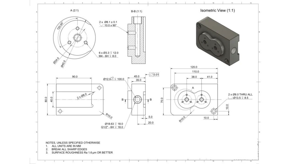
Threaded holes or shafts, dimensions with tolerances, specific surface finish requirements—these all need to be known to the CNC machine operator.
Here are some practical experiences:
When designing parts, try to use tools with larger diameters.
All internal vertical corners should have a large radius (at least 1/3 of the cavity depth).
The depth of the cavity should not exceed 4 times its width.
It is best to design the main features of a part along one of the six main directions (front, back, left, right, up, and down). If this is not possible, then choose 5-axis CNC machining.
If your design has thread requirements, tolerances, surface finish requirements, or other things you need to tell the operator, remember to attach a technical drawing when you submit it.