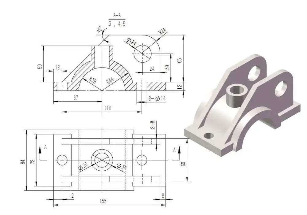
CNC process introduction
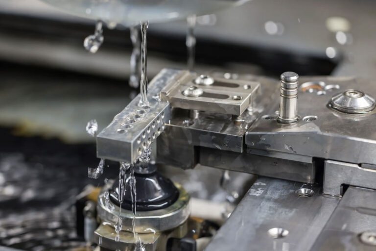
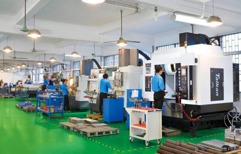
Computer numerical control (CNC) machining is a subtractive manufacturing method that uses a number of high-speed, precision machines to achieve the desired structure. Essentially, sections of a block of material are gradually removed using a variety of methods, including cutting, drilling, beveling, and slotting.
As with all manufacturing processes, better results can be achieved by considering the specifics of CNC machining during the design phase . After a brief review of the types of CNC machines, this article will detail some of the design aspects.
Types of CNC Machine Tools
Some common types of CNC machines include:
Lathes: Commonly used to create complex cylindrical shapes, they are the preferred choice for many designs due to their cost-effective operation. The material rotates while the cutting tool remains stationary. The creation of the geometry relies on the motion and feed rate of the stationary tool and the control of the material’s rotational speed.
Vertical milling machine: The spindle axis (and cutting tool) is aligned perpendicular to the machine bed. Unlike a lathe, the cutting tool moves.
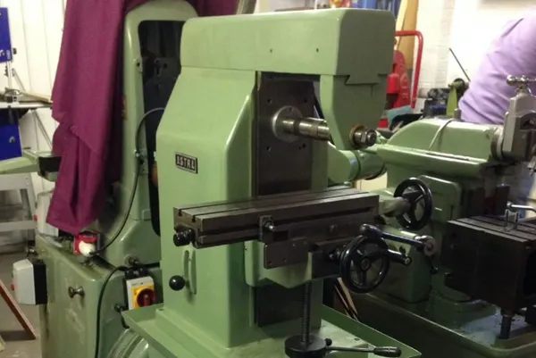
Horizontal milling machines: The cutter is mounted on a horizontal spindle on a work table. They are used when the cutter needs to remove a large amount of material or when less precision is required.
Router: Similar to a vertical milling machine, the cutting tool is aligned perpendicular to the machine bed and the router moves while the part remains stationary. The main difference is the ratio of the work area to the machine, which is almost 1:1 for a router but closer to 1:3 for a milling machine.
For all of the above machines, a variety of high-speed cutting tools are used to perform the different processes required to remove material from a solid block of metal or plastic. Most cutting tools used for CNC machining have a cylindrical shank with a specific tip shape and a limited overall cutting length.
As material is removed from the workpiece, the tool’s geometry is transferred to the part. This means that internal features on CNC machined parts always have corner radii, no matter how small the cutting tool selected for the process.
CNC material introduction

Material selection is crucial in determining the cost of a part. Properties to consider when selecting them for machining include hardness, rigidity, and chemical resistance, as well as other mechanical and aesthetic qualities.
Common metals used for machining include:
Steel: All steel is composed of iron and carbon. The carbon content and any additional alloying properties determine the properties of each steel grade. A wide variety of grades and types are available to suit a wide range of applications. Well-processed grades include stainless steels 304 and 316, which offer formability, weldability, and corrosion resistance, as well as 4130, which provides sufficient strength, toughness, and fatigue resistance for use in military and commercial aircraft parts.
Aluminum: Aluminum is the world’s most abundant metal. In its pure form, it is soft, ductile, corrosion-resistant, and highly conductive. Aluminum can also be alloyed with other metals to enhance certain properties. Key grades used for machining include 6082 (excellent corrosion resistance and the strongest of the 6000 series alloys) and 6061 (good corrosion resistance, formability, and weldability).
Brass: Brass offers high strength, high machinability, and corrosion resistance. These properties make it an ideal material for low-pressure hydraulic connectors and low-friction items such as locks and ammunition. Due to its similarity to gold, it is also widely used for decorative purposes.
Copper: Its excellent electrical conductivity makes it ideal for electrical products such as busbars and motors, but it is also used in radiators, roofing, and gutters due to its corrosion resistance. Machining copper is generally a simple process as it is a good thermal conductor and can be easily formed.
The range of plastics that can be processed includes:
Nylon: Nylon is a synthetic thermoplastic linear polyamide available in a range of grades, similar to steel and aluminum. Key properties include good machinability, high compressive strength, and high friction resistance. It’s also a very economical choice. In certain applications, it can replace metal, providing a longer-lasting, lower-maintenance solution.
PTFE: PTFE, commonly known as Teflon, offers excellent abrasion resistance, making it an ideal choice for parts requiring durability and high impact strength. Unlike other processed plastics like nylon, PTFE has a very low moisture absorption rate, making it well-suited for humid environments. Key applications include insulators, valve components, bearings, and gaskets.
PEEK: Polyetheretherketone (PEEK) is well-suited for high-strength and high-stiffness applications. Additionally, PEEK offers high resistance to heat, moisture cycling, and chemicals, making it an ideal choice for pump components, medical implants, and aerospace parts.
Others such as ABS/PC plastics, etc.
CNC Design Points
1, Tolerance and fit
Tolerances define the acceptable range for any given dimension. If no overall tolerance is defined, most machine shops will use a standard tolerance of ±0.125 mm, but it is often important to define your own standard, as applications may require tighter tolerances than this.
A fit can be referred to as the correct application of tolerances and is designated as either a shaft-based fit or a hole-based fit. Fits can be divided into three categories:
Clearance fit: The hole is larger than the shaft, allowing the two parts to slide or rotate when assembled.
Transition fit: The hole is the same size as the shaft or slightly smaller, requiring very little force for installation or removal.
Interference fit: The hole is smaller than the shaft, requiring a lot of force (or heat) to assemble or disassemble.
Specific tolerances should be used only when you need to control the fit of two or more mating parts. The following example includes all three fits:
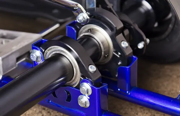
Bearing to housing: Inserting the bearing into the housing where the outer ring remains stationary and the inner ring is allowed to rotate requires an interference fit or a transition fit (depending on the material used in the housing).
Shaft to Bearing: Bearings are often specified as transition fits or slight clearance fits to allow for round-to-integer design of any shaft. It is important to check the bearing specifications and assembly in a CAD package to quickly flag any potential issues before manufacturing.
Mounting the housing: Assuming the housing is rigidly mounted to the frame, the holes used to mate the two components need to meet specific clearances.
But assuming the housing is one of three set across a larger frame, and there is a long shaft (or axle) running through all the housings, how do you control the clearance of the mounting holes and the concentricity of the shaft bearings?
This is where Geometric Dimensioning and Tolerancing (GD&T), which uses a symbolic language to explicitly describe nominal geometry and allowed variations, comes in. For the example above, you could use concentricity or position features to control the fit.
While standard tolerances are often sufficient for part designs, certain geometric features used in GD&T (flatness, straightness, cylindricity, concentricity, etc.) are necessary for more complex parts where features affect each other. Be sure to avoid any unnecessarily tight tolerances, as these may increase part cost by slowing down the machine, requiring additional fixtures, or requiring special measuring tools.
2, Holes and threads
Hole
Drill depth: Keep drilling depth low to avoid the use of specialist tools and do not specify flat bottom holes unless absolutely necessary
Extended Holes: Extended holes can be drilled from both sides of the part. However, it is important to realize that there will be a mismatch where the two holes meet, which can be resolved by using a fixture, but this will increase the cost of the part.
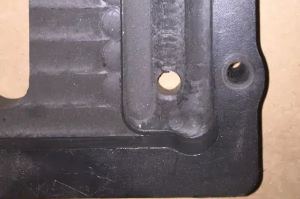
Edge drilling: For edge drilling, ensure the entire diameter of the drill bit is contained within the part. If any portion of the diameter is outside, the drill bit may break, the surface finish will be poor, and the resulting sharp edges at corners may fold. If absolutely necessary, drill the part first, then mill away material to leave a partial hole.
Number of threads
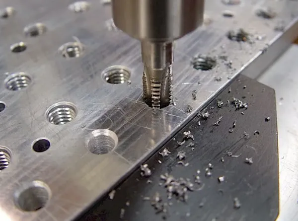
Methods: There are three main ways to create threads.
Cutting Tap: The female part of a tap that forms the mating pair by removing material from the hole.
Forming taps: Create threads by displacing material within a hole.
Thread milling cutters use helical interpolation to create threads by inserting along the spindle axis.
Hole Type: For threaded holes, a through hole is ideal, as this allows the tap to pass completely through the part and ensures accurate thread creation. For blind holes, add 1.5 times the nominal diameter of the hole bottom to the thread length.
Thread Size: Be sure to select the largest possible thread size due to ease of manufacturing. Smaller taps mean a greater chance of breakage during production.
Thread Depth: Machine parts only to the necessary length, as deeper threads increase cost, while off-the-shelf sizes can reduce costs. Ask your chosen machine shop which threads they carry.
Drawing Details: Indicate the threads to be added to the quote and include an accurate 2D drawing detailing all threads to avoid confusion and ensure the part you receive is as designed.
3, Chamfers and fillets
Chamfer: A bevel cut where two surfaces meet where sharp edges meet, to simplify assembly (inserting a bolt into a hole) and reduce the risk of injury when handling sharp objects.
Fillet: A rounded corner on the inside or outside of a part. This feature is usually the result of the tool radius. It is important to keep any radius on the part larger than the tool radius as this will make the machining process simpler.
Deburring: Note that there is a difference between chamfering and deburring. Machinists will only break the edge of a part to remove burrs, but if a specific size is required, they will chamfer the material. Chamfered edges should be kept at 45° unless a different angle is required.
Internal fillet: The internal fillet should be as large as possible to allow the use of large diameter tools, thereby reducing machining time. Generally, the internal fillet radius should be greater than 1/3 of the cavity depth to avoid breaking the tool.
Dog bone corner: If the mating part requires a square corner, a dog bone corner can be used to remove material around the corner. For ease of manufacturing, the corner diameter should be as large as possible.
Bottom edge fillet: When creating a radius on the bottom of a cavity, it is easier to machine it with a smaller radius than on the walls. This allows the same tool to be used, resulting in a smooth flow around the corners.
4, Undercut
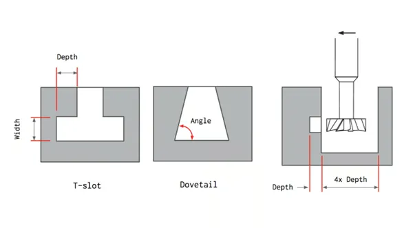
Undercuts are features that cannot be machined with standard cutting tools because some of their surfaces are not directly accessible from above. There are two main types of undercut features:
T-slots: Cutting tools consist of a horizontal cutting insert attached to a vertical axis. To limit cost increases in these cases, use whole millimeter increments or standard fractions of an inch for tool widths.
Dovetail: Cutting tools use angle as a defining feature, with standard tools at 45° or 60° (tools up to 120° in 10° increments are also available).
When machining, it is best to avoid undercuts, as they are difficult to machine and require specialized tools or multiple setups. If absolutely necessary, keep undercuts as small as possible.
For undercuts on interior walls, allow ample clearance for the tool. Add a space between the machined wall and any other interior walls equal to at least four times the depth of the undercut.
Surface treatment
The most common surface finishes for CNC machined parts are as follows:
Milling: Due to the nature of CNC machining, some tool marks will appear on the part surface. Surface quality is measured by average surface roughness, defined as the average deviation of the machined profile from the ideal theoretical surface. This finish provides the tightest dimensional tolerances and is available at no additional cost, but visible tool marks from milling can detract from the part’s aesthetics.
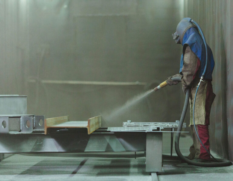
Bead blasting: Using a pressurized air gun, a part is bombarded with small glass beads, removing some material and smoothing the exposed surfaces of the part, resulting in a uniform matte or satin surface finish. Critical surfaces and features can be masked to avoid any unwanted dimensional changes. The manual nature of this process means that the quality of the finish depends largely on the skill of the operator, but a variety of finishes can be produced depending on the size of the glass beads used (from coarse to very fine, similar to sandpaper grades). Bead blasting can also help relieve some of the stress concentrations left by the machining process, which is very useful for mechanically strained components, such as pistons, as any concentrated stress greater than the material’s strength in a given area has the potential to produce fatigue cracks.
Anodizing: The process of forming an oxide film on aluminum or titanium parts in a chemical solution called an electrolyte. There are different types:
Type I is a chromic acid anodized film used for aerospace and other precision-machined components. It is ideal for welded assemblies. This process typically uses black dye, as other colors are less practical. This topcoat can also be used as a primer for a higher-quality powder coat finish.
Type II involves diluted sulfuric acid and is known as “standard” or “decorative” anodizing. It produces parts with a smooth surface, good corrosion resistance, and limited wear resistance, but is still suitable for parts requiring tight tolerances.
Type III also uses dilute sulfuric acid, but it is a “hard coating” that produces a thick ceramic coating with very high corrosion and wear resistance, and is mainly used for sliding parts and hinge mechanisms and other mechanically stressed parts such as valves and pistons.
Powder coating: Adds a thin layer of protective “paint” (a dry powder, not a liquid spray) to the surface of a part, providing a strong and wear-resistant finish compatible with all types of metal. Powder-coated parts offer higher impact resistance than anodized parts, as multiple layers of powder coating can be applied in a variety of colors. However, this does result in less dimensional control than anodizing. Additionally, due to the nature of the application, coating internal features and surfaces is not easy.
Electroplating: The application of one or more layers of metal to a component by passing a positively charged electrical current through a solution containing dissolved metal ions (the anode) and a negatively charged current through the component (the cathode). The use of single metals such as tin, lead, and zinc, as well as more aesthetically pleasing metals such as gold and silver, allows for the addition of customized properties. This process is often used for finishing medical diagnostic instruments, electronics, and optical devices.
Other specialist surface treatments are also available, such as dry lubricants (which reduce friction) and other performance-enhancing surface treatments, so it is important to perform due diligence on your application.
Precautions
Thin walls: Difficult to machine and prone to breakage, thin wall machining requires multiple passes with low cutting depths, which increases costs. Thin wall features are also prone to vibration, making machining precise thin walls very challenging and time-consuming.
Deep cavities: Cavity depth should be kept below four times the tool diameter to reduce machining difficulty and the possibility of tool breakage.
Small features , such as microvias (less than 2.5 mm in diameter), increase machining difficulty and time, negatively impacting costs during the process.
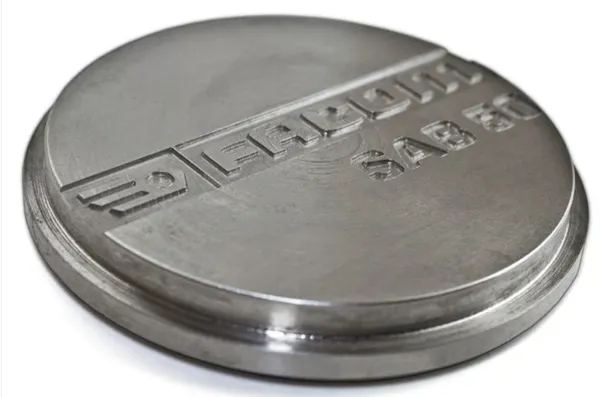
Embossed Text: Because a large amount of material needs to be removed during this process, it is best to use engraved text. It is also recommended to use a sans-serif font with a minimum size of 20 points to avoid small features appearing in the engraved text.
Specific tolerances for non-critical features: The greater the precision required to machine a part, the higher the cost of the finished part due to increased machining time and labor. Specific tolerances should be defined with caution and only when using standard tolerances on technical drawings is unacceptable.