Aluminum Alloy Engraving Tool Design
The design of aluminum alloy engraving tools (mostly small-diameter end mills, φ8mm and below) needs to be optimized by combining material properties, machining requirements, and tool geometry parameters. The key points are as follows:
1, Selection of cutting tool materials
Common materials
High-speed steel (such as W18Cr4V), cemented carbide (such as YG6X ultrafine grain tungsten cobalt), polycrystalline diamond (PCD), diamond-like carbon (DLC coating), etc.
Feature requirements
High hardness (≥60HRC), high wear resistance, sufficient strength and toughness, good machinability and economy. PCD tools are suitable for finishing high silicon aluminum alloys due to their high hardness (HV10000), low coefficient of friction (about half that of cemented carbide) and low coefficient of thermal expansion; DLC coating can reduce cutting forces (axial force reduced by 2/3) and reduce built-up edge.
2, Geometric parameter design
Anterior angle (γ₀)
Aluminum alloys have low strength and are prone to sticking to the cutting tool, requiring a large rake angle (12°~15° for roughing and 15°~20° for finishing) to reduce cutting force and avoid built-up edge.
Back angle (α₀)
Aluminum alloys have a low elastic modulus (about 1/3 that of 45 steel), and the elastic recovery leads to severe friction on the back face, requiring a large back angle (8°~10° for roughing, 10°~12° for finishing; finishing can be increased to 15°~20°).
Helix angle (β)
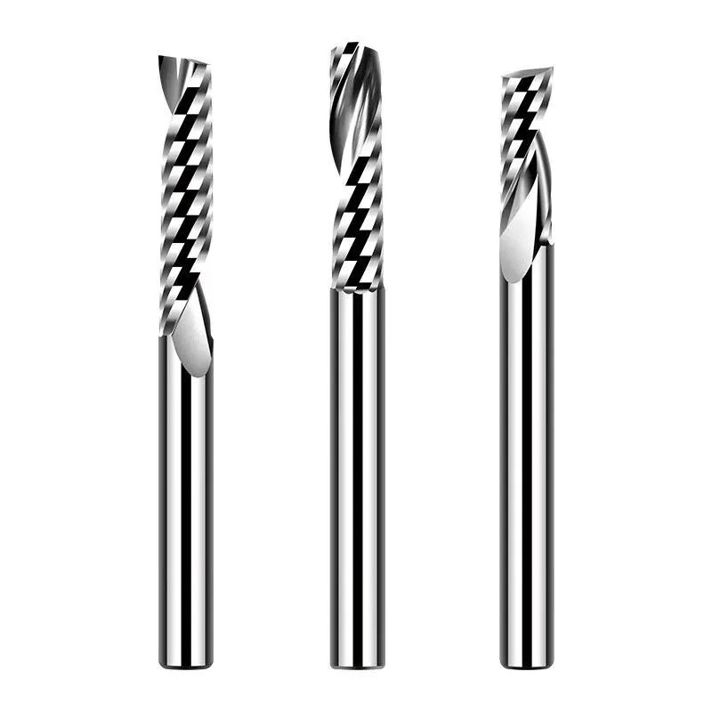
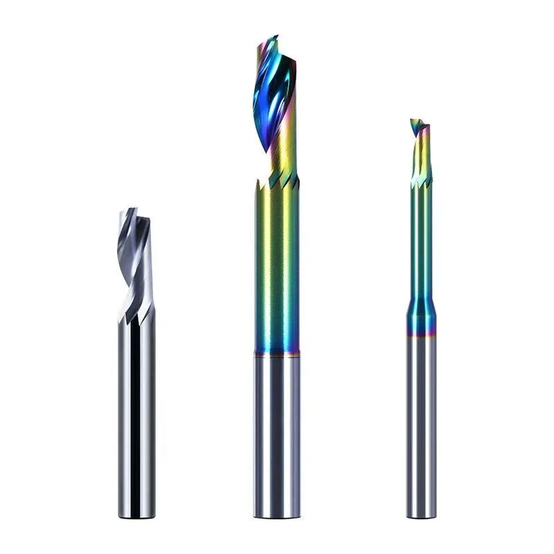
A large helix angle (35°~50°) can reduce radial cutting force and improve chip removal. For roughing, a 40°~50° angle (three-flute wave end mill) is recommended, and for finishing, a 25°~30° angle (two-flute end mill).
Edge treatment
For fine finishing, a sharp cutting edge is required to avoid a blunt or rounded edge; a slight chamfer (width 0.1~0.3mm, rake angle -6°~-20°) can be used to enhance the strength of the cutting edge and prevent chipping.
Core thickness and chip groove
The core thickness should be 45%~50% of the outer diameter of the tool (e.g., the core thickness of a φ6mm tool is about 3mm) to increase the chip space and prevent chip clogging; the chip evacuation groove needs to be polished (Ra≤0.4μm) to reduce friction.
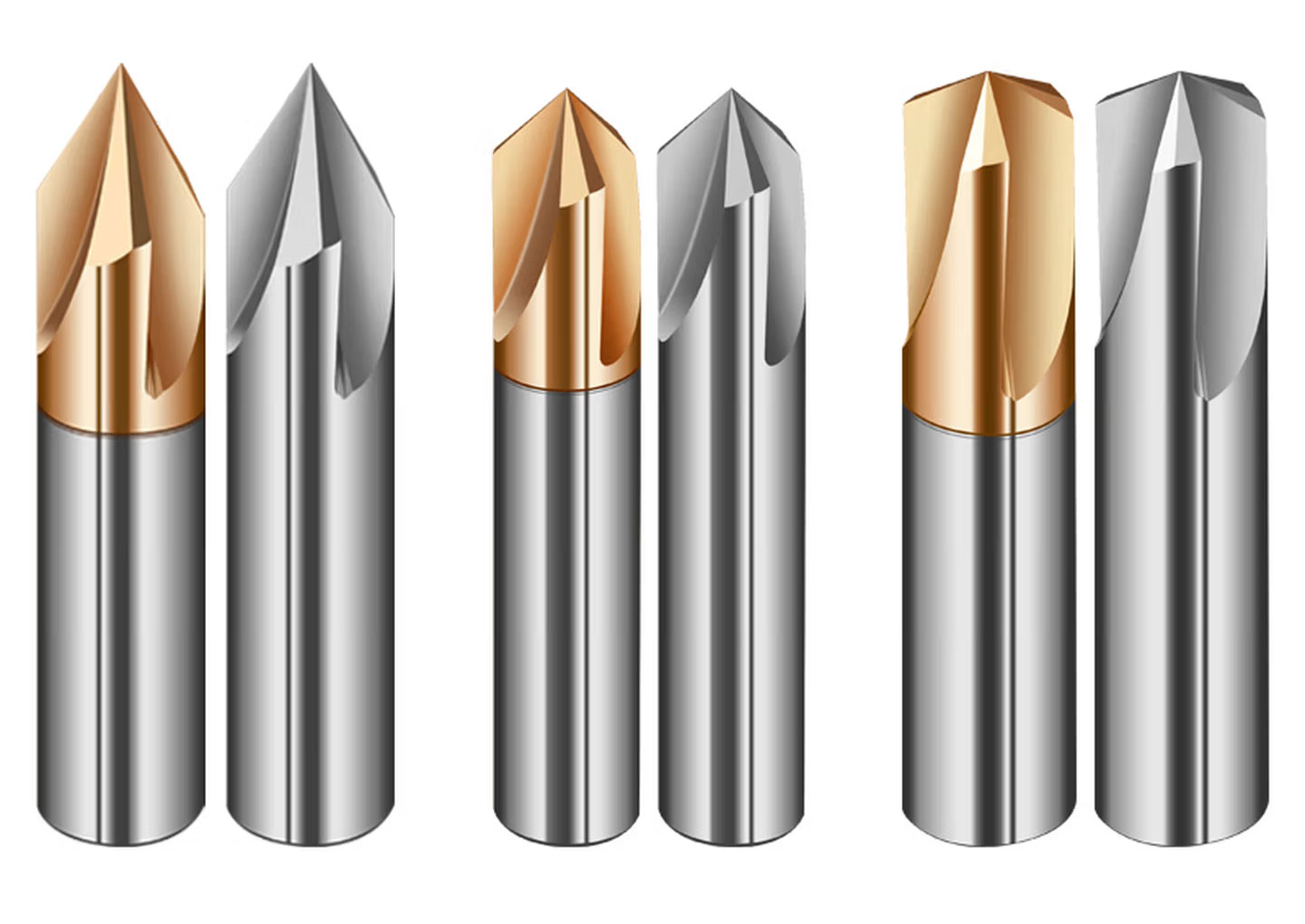
Special design
Three-flute aluminum end mills adopt a main end-edge + secondary end-edge structure (the main end-edge passes through the center, while the secondary end-edge does not), reducing repeated cutting at the center and improving chip removal efficiency; ball end mills must ensure the symmetry of the cutting edges, and the radius of the radius of curvature must match the cutting depth (usually 0.5~2mm).
3, Surface roughness and coating
The tool surfaces (rake face and flank face) need to have a high surface finish (Ra≤0.4μm) to reduce chip adhesion; the rake face of finishing tools can be polished to Ra≤0.1μm.
Coating selection: DLC coating (friction coefficient μ=0.005~0.2) has good anti-adhesion properties; diamond coating (temperature resistance above 800℃) is suitable for high-speed cutting of high silicon aluminum alloys; avoid TiAlN coating (it will cause diffusion wear with aluminum).
4, Cutting parameter optimization
Rotational speed
Aluminum alloys have good thermal conductivity and are suitable for high-speed cutting (16000~24000rpm); when using PCD tools, the cutting speed of high-silicon aluminum alloys can reach more than 5000m/min.
Feed rate
For small diameter tools (φ3~6mm), the feed rate is 0.03~0.15mm/tooth, and for large diameter tools (φ10~25mm), it is 0.15~0.30mm/tooth. For finishing, the feed rate is reduced to decrease surface roughness.
Depth of cut
For roughing, ap ≤ 1 × D (tool diameter); for finishing, ap ≤ 0.1 × D. Thin-walled parts require a smaller depth of cut (≤ 0.5 mm) to reduce deformation.
Inspection of Aluminum Alloy Engraving Tools
The inspection must cover appearance, dimensions, geometric parameters, surface roughness, and dynamic accuracy to ensure that the cutting tools meet the requirements.
1, Visual inspection
Visually inspect the tool surface for defects such as flaws, scratches, cracks, burrs, black spots, burns, and rust; sharp edges of non-cutting parts should be blunted.
2, Dimensional Inspection
Total length and working length
Use calipers or a steel ruler to measure along the axial direction, with accuracy according to the tool requirements (e.g., IT7 grade).
Outer diameter
Even-numbered cutting edges are measured with a symmetrical micrometer (near the tip); odd-numbered cutting edges are measured with a three-groove/five-groove micrometer or a laser cutting tool measuring instrument.
Handle diameter
Take 3 to 5 measurements on the handle of the micrometer and record the maximum deviation value (e.g., h6 precision).
Core thickness and blade length
Use calipers or micrometers to measure the core thickness (45%~50% of the outer diameter) and the blade length (finished blade length + 0.5mm).
3, Geometric parameter detection
Front corner/back corner
Scan the normal section of the cutting edge using a surface profilometer or tool measuring equipment, and take the average of three measurements (graduation value 0.01°).
Helix angle
Analyze the cutting edge helix using a tool microscope or dedicated measurement software (such as VM-2D) and calculate the angle (tolerance ±1°~±5°).
Blade tip radius
The laser confocal microscope (gradient value 0.0002mm) scans the scalpel tip arc and takes the average of three measurements (e.g., Ra 0.2~0.8mm).
Blade height difference
The difference between all cutting edges of the drill/end mill at the same point should be ≤0.02~0.05mm (measured with a lever gauge).
4, Surface roughness inspection
A small-size 3D measuring instrument is used to detect the surface roughness of the rake face, flank face, and cutting edge (Ra≤0.4μm, Ra≤0.1μm for finishing).
5, Dynamic accuracy detection
Radial runout
After the tool and tool holder are assembled, a tool measuring instrument (such as GENIUS3) is installed to rotate and detect radial runout; the tool insertion position is adjusted to compensate for the error between the tool holder and the tool (patent CN201310657995).
Wear and chipping
Observe the back face wear (VB≤0.1mm is the dull standard) and chipping length/width (take the maximum value) using a tool microscope.
Final Words From Gaofeng
The design of aluminum alloy engraving tools requires key optimization of materials (PCD/carbide), geometric parameters (large rake angle/clearance angle/helix angle) and surface treatment (high gloss/coating). Inspection needs to cover appearance, dimensions, geometric parameters and dynamic accuracy to ensure machining quality and tool life.