Ⅰ, General principles of toolpath:
Roughing:
During roughing, the machine should operate at or near its maximum load capacity.
In most cases:
Use the largest possible cutter.
Apply the maximum possible depth of cut.
Use the fastest feasible feed rate.
For a given tool, the feed rate is inversely proportional to the depth of cut.
Generally, machine load is not a limiting factor. Tool selection should primarily consider whether the 2D corners or 3D curves of the part are too small to accommodate the cutter.
Once the tool is selected, determine the tool length.
The cutter length must be greater than the machining depth.
For large workpieces, consider whether the tool holder or chuck may interfere with the part.
Finishing (Finishing Tool / Light Cut)
The purpose of finishing is to achieve:
The required surface finish of the workpiece.
Proper stock allowance for subsequent operations.
Similarly, for finishing:
Use the largest feasible tool.
Minimize machining time by using the fastest safe feed rate.
Select appropriate depths of cut and feed for precision machining.
Notes on finishing feed:
For the same feed rate, a larger step-over results in faster lateral machining.
The depth of cut on curved surfaces affects the final surface quality.
Feed rates should be chosen according to the surface geometry.
Always leave the minimum stock required, use the largest cutter possible, the highest spindle speed, and an appropriate feed, without damaging the surface.
Ⅱ, Clamping method:
All clamping is long horizontally and short vertically.
Vise Clamping:
The clamping height should be no less than 10 mm. The clamping height and processing height must be specified when machining the workpiece.
The processing height should be approximately 5 mm above the vise plane to ensure firmness while protecting the vise. This type of clamping is general, and the clamping height also depends on the size of the workpiece; larger workpieces require a higher clamping height.
Clamping with plywood:
The plywood is mounted on the workbench with a code, and the workpiece is locked on the plywood with screws. This type of clamping is suitable for workpieces with insufficient clamping height and large processing force, and generally has a better effect on medium and large workpieces.
Clamping with a staking iron:
When the workpiece is large, the clamping height is insufficient, and screw threading at the bottom is not permitted, staking iron clamping is used. This clamping method requires a second clamping process.
First, staking the four corners, then machining the rest of the workpiece. Then, staking the four sides and machining the four corners.
During the second clamping process, do not allow the workpiece to become loose; staking first, then loosening. Alternatively, staking two sides first and machining the other two.
Tool clamping:
For tools with a diameter of 10 mm or more, the clamping length should be no less than 30 mm; for tools with a diameter of 10 mm or less, the clamping length should be no less than 20 mm. The tool should be clamped securely to prevent collisions and direct insertion into the workpiece.
III. Classification of Cutting Tools and Their Applications
1, By Material
High-Speed Steel (HSS) Tools:
Easily worn; used for copper electrodes and small steel roughing.
Carbide Tools (Tungsten Carbide):
Used for corner cleaning (especially on steel) and finishing operations.
Alloy Tools:
Similar applications as tungsten carbide tools.
Purple Steel Tools:
Used for high-speed cutting; highly wear-resistant.
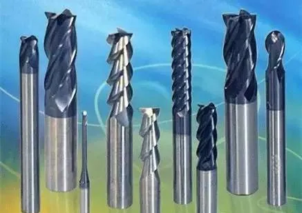
2, By Tool Tip
Flat-End Mill:
Used for planar surfaces and straight sides; suitable for cleaning flat corners.
Ball-End Mill:
Used for semi-finishing and finishing of various curved surfaces.
Bull-Nose End Mill (single-sided, double-sided, five-sided):
Used for steel roughing, with typical corner radii of R0.8, R0.3, R0.5, R0.4.
Roughing End Mill:
Used for roughing operations; pay attention to stock allowance (typically 0.3 mm).
3, By Shank Type
Straight Shank Tools:
Suitable for all applications.
Tapered Shank Tools:
Not suitable for straight side surfaces or surfaces with a slope smaller than the taper angle.
4, By Number of Flutes
Two, Three, or Four Flutes:
The more flutes, the better the cutting performance, but also more machining work required.
Spindle speed and feed must be adjusted accordingly.
Tools with more flutes generally have longer tool life.
5, Difference Between Ball-End Mills and “Flying” Finishing Tools
Ball-End Mill:
If the radius of the concave surface is smaller than the ball radius, or if the flat surface is smaller than the ball radius, it cannot reach the bottom corners.
Flying Tool (Fly Cutter / Sweep Finisher):
Advantage: Can reach and clean bottom corners.
Comparison with same parameters: V = R × ω, fly cutters can achieve much higher spindle speeds.
Produces brighter, smoother surfaces, with higher cutting force.
Often used for Z-level (constant-Z) roughing/finishing, sometimes eliminating the need for semi-finishing.
Limitation: If concave or flat surface dimensions are smaller than the fly cutter diameter, it cannot reach these areas.
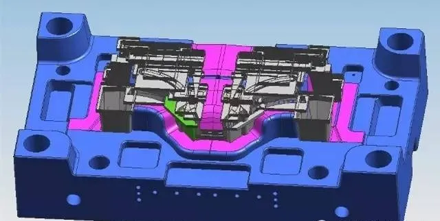
Ⅳ, CNC Machining with EDM — Making Copper Electrodes
1, When Copper Electrodes Are Needed:
When the cutting tool cannot reach a certain area, a copper electrode (also called electrode or EDM electrode) must be made.
If even within one electrode there are still unreachable areas, and the shape is raised, then it needs to be split into multiple electrodes.
If the tool can technically reach but is likely to break easily, an electrode may still be required — this should be decided based on the actual situation.
Products that require EDM texture (spark marks) on the surface must use copper electrodes.
When the electrode itself cannot be made due to thin or tall ribs, which can easily cause deformation or damage during machining or EDM, inserts are required instead.
Surfaces produced by copper electrodes (especially curved surfaces) are smoother and more uniform, which helps to overcome many issues in fine milling and design.
When highly precise external shapes or large material allowances are needed, a rough electrode must be made first.
2, How to Make Copper Electrodes:
Select the surfaces that require copper electrodes, fill or extend any incomplete or missing surfaces to ensure all electrode edges are larger than the intended EDM area and do not interfere with other product surfaces.
Remove unnecessary flat corner areas that cannot be cleaned (at intersections of flat surfaces and deep ribs), and reshape them into regular, simple forms.
Determine the maximum external outline of the electrode, use it as the boundary, and project it onto the base surface.
Define the reference frame size, trim off the base surface, and by this stage, the electrode drawing is basically complete.
Prepare the electrode material:
Length × Width × Height
Length and Width ≥ Ymax and Xmax (the actual copper block must be larger than the reference frame on the drawing).
Height ≥ theoretical electrode height + reference frame height + clamping height.
V, Drawing and Coordinate Setup Guidelines
1, When No Pre-Machined Reference Surface Exists
For raw materials without existing machined surfaces:
Center the workpiece in X and Y directions (four-side centering).
Set the center as the origin (X0, Y0).
Set the top surface as Z0.
If the top surface is uneven (such as for copper electrodes), leave 0.1 mm stock allowance.
This means when probing (“touching off”), the actual Z0 is set to the top surface, but the drawing Z0 should be offset 0.1 mm lower.
2, When a Pre-Machined Surface Exists
If the workpiece already has a machined reference surface:
Set the existing machined surface on the drawing to Z0.
If the plane allows centering, center it; if not, align based on a single reference edge.
Verify the actual height, width, and length against the drawing dimensions, and program according to the actual stock size.
As a general rule: first machine the workpiece to the drawing dimensions, then proceed with the contour and shape machining.
3, Multiple-Position Machining
When multiple setups are required for different machining positions:
The first setup (standard position) must include machining the reference surfaces for all subsequent setups.
Ensure all length, width, and height reference surfaces are milled flat and accurate.
Every following machining operation must use the previously machined reference surfaces as its datum.
4,Insert Positioning (Inlay Components)
For inserts or inlay components:
Position the insert inside the main body, raising it by a specified height using spacers.
The drawing Z0 should also be shifted upward by this same height.
The plane should be centered according to the main body; the height should be defined on the drawing.
The insert is then locked in place with screws from below.
If the insert is square and symmetrical, it can be directly centered.
For a rough setup, use the maximum external profile for centering.
When using a custom fixture, define the insert’s position relative to the fixture.
Then, set the drawing origin (0,0,0) to the center of the fixture for programming consistency.
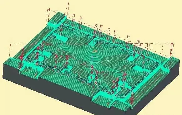
VI. Roughing Toolpath Selection
1,Surface Pocketing (3D Roughing)
The key to effective roughing lies in proper area and surface selection.
The machining area should include all reachable regions between the highest and lowest points within the selected range, using the chosen surface as the termination boundary.
Ideally, select all related surfaces; the boundary should cover only the intended machining area.
If no surface is selected in certain areas, extend the boundary by less than half of the tool diameter—this ensures sufficient stock remains for automatic protection on adjacent surfaces.
It is best to extend the path slightly below the lowest contour, as a small corner radius (R) may otherwise remain uncut.
Tool Selection:
If the tool cannot enter by helical or linear ramping, or if some regions are inaccessible, seal those areas and leave them for secondary roughing.
Before the finishing stage, ensure that all uncut areas are fully rough-machined—especially small 2D and 3D corners, and sealed areas—to prevent tool breakage.
Secondary Roughing:
Typically uses 3D pocketing within a defined range, with a flat-end mill.
Where possible, use planar pocketing or profile toolpaths.
To avoid damaging other surfaces, the tool center should reach the selected boundary without additional boundary finishing.
Use high-speed bidirectional toolpaths, adjust cutting angle as needed.
For entry, use helical ramping (1.5° angle, depth = 1× tool diameter).
If the slot shape prevents helical entry, use linear ramping instead.
Enable toolpath filtering, especially in curved surface roughing.
Keep the entry plane high enough to avoid collisions, and set a safe retract height—never too low.
Tool Retraction:
Usually use absolute retraction rather than relative.
However, if there are no islands, relative retract can be applied.
2, Planar Pocketing
Used for machining flat surfaces and recessed pockets.
When milling partially open planes, define boundaries carefully.
The key principle is ensuring tool entry space greater than one tool diameter.
For open areas, offset the entry boundary outward by more than half a tool diameter; for closed areas, fully seal the outer boundary.
3, Contour Machining (Profile Roughing)
When the selected surface is suitable for layered contour machining, use step-up contour toolpaths (planar contouring).
If the entry point and retract point are the same, retracting to the Z-plane is unnecessary.
Avoid using relative height for retracts whenever possible.
Typically use right compensation (G41/G42 right offset), i.e., climb milling direction.
4, Machine Compensation Toolpath Setting
Use compensation number 21 for mechanical compensation.
Switch from computer compensation to machine compensation mode.
Tool entry should be vertical.
For areas the tool cannot reach, increase the corner radius (R) and remove all remaining stock.
5, Constant-Z Contour (Z-Level Roughing)
Best suited for closed surfaces.
For open surfaces, if there are four contours, seal the top surface.
If there are fewer than four contours, or for non-standard cases, select machining range and height.
Always use arc lead-in for roughing to ensure smooth entry.
Use constant-Z roughing when the machining distance within any plane is smaller than one tool diameter.
If it exceeds one tool diameter, use a larger tool or perform two-step Z-level roughing.
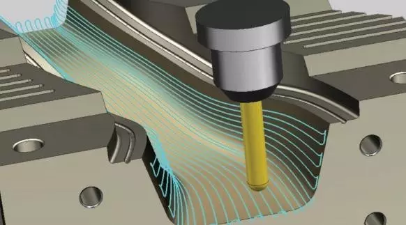
6, Flowline Toolpath
This toolpath provides the best uniformity and smoothness.
It’s ideal for finishing operations, and in many cases, can replace constant-Z contouring for better surface results.
7, Radial Toolpath
This method is suitable for parts with a large central hole (used less frequently).
Notes:
Avoid tool deflection or chatter.
Ensure the tool is sharp and not excessively long.
For deep cavities, use spiral or circumferential paths, not vertical plunging.
At sharp corners, divide toolpaths into two separate sides—do not cut across the intersection.
During finishing, extend the edge where possible, and use arc lead-in/lead-out motions for smoother transitions.
VII. Corner Cleaning (Rest Machining)
2D Corner Cleaning:
This step removes the 2D dead corners that previous toolpaths could not reach.
Areas that will later be machined by the finishing tool (finishing cutter) should have their corners cleaned before the finishing operation.
For deep and narrow corners, use multiple tools in sequence rather than trying to clear everything with a single small cutter. Avoid using a fragile small tool to machine too many areas.
3D Corner Cleaning:
This process targets small grooves and 3D transition corners that remain after semi-finishing or finishing operations.
Tool Breakage Prevention:
Be cautious when using thin or long tools, especially in cases involving heavy Z-direction cutting (deep vertical machining).
These situations easily cause tool breakage, so appropriate depth, step-down, and feed settings are essential.
Toolpath Strategies:
Use 2D contour toolpaths for cleaning small 2D corners (around R0.8) and flat planar corners.
Use parallel toolpaths or constant-Z (Z-level) toolpaths for 3D areas.
For areas inaccessible by the tool or small dead corners that cannot be reached by outer contour paths, first seal these regions temporarily, then clean them at the final stage.
Small gaps or recesses on large surfaces should also be sealed first and then cleaned later to ensure smooth tool movement and surface quality.
VIII. Semi-Finishing
Definition:
The semi-finishing process is applied to steel or fine material surfaces, serving as an intermediate step between roughing and finishing.
Purpose:
During rough machining, the large cutter usually leaves a considerable amount of stock between layers.
Semi-finishing removes this excess material, ensuring better surface accuracy and uniformity before the final finishing stage.
Characteristics:
Fast material removal with high feed rates and large stepovers.
Can use large or fly cutters (face mills).
Surface finish is not a priority at this stage.
Flat surfaces generally do not require semi-finishing.
Constant-Z contour parts also may skip semi-finishing; in such cases, slightly finer roughing can combine both operations.
“Finer” means reduced stock allowance and smaller step-downs between layers.
The necessity of semi-finishing also depends on material hardness — the harder the material, the more important the semi-finishing step.
Ideally, the semi-finishing toolpath direction should be opposite to the finishing toolpath direction.
This results in more balanced cutting forces and a smoother final surface.
Ⅸ, Finishing Tool Operation Guidelines
The finishing process must be carried out with great care, as it directly affects the assembly precision of products and molds. Different requirements call for different toolpath strategies and parameter settings.
1, Tool Height and Tolerance Settings
Both the cutting start height and the final height should be set to 0.
Tolerance should be controlled within 0.01 mm (depending on part size; the smaller the part, the tighter the tolerance). No filtering is required, as tolerance directly affects the final contour accuracy.
2, Surface Finish Requirements
The core side and parting surface must achieve the best possible surface finish.
The cavity side may allow slightly lower surface quality.
Other non-fitting or clearance areas can remain relatively rough.
3, Toolpath Design Considerations
Toolpath strategy depends on several factors:
Part geometry, such as planar or curved surfaces.
Surface steepness, distinguishing between steep and shallow regions.
Sharp corners between surfaces (sharp transitions should be machined separately).
Different surface requirements, including stock allowance and finish quality.
Surface protection during finishing is extremely important. All previously machined surfaces must be protected to compensate for any potential machining errors.
Protection may include:
Defined protection ranges (both in height and planar directions).
0-tolerance protection where no deviation is allowed.
Surface range protection to prevent overcutting.
4, Toolpath Extension
When the toolpath reaches an edge, it’s best to add an arc lead-in/lead-out movement to ensure smooth transition. Alternatively, slightly extend the surface before machining to avoid tool marks at the boundaries.
5,Tool Lifting Optimization
Tool retraction wastes machining time, so it should be minimized whenever possible.
Methods to reduce tool lifting:
Set small retract clearances for minor gaps.
Seal small gaps to avoid unnecessary lifting.
Bypass large gaps by adjusting the toolpath.
For constant-height contours, extend the path to the same level.
Tool Wear Management
When machining large parts, use multiple tools to complete the same finishing process, ensuring consistent surface quality and avoiding excessive tool wear.
Tool Entry Strategy
The first cut must always enter from outside the workpiece to prevent vibration or surface damage. Every finishing toolpath should include a proper lead-in motion.