Introduction
Mechanical structure engineers should be familiar with prototypes, but for those who have not been exposed to this industry or junior engineers who have just graduated, they have not participated in the entire process of product development. Most of them probably don’t know what a prototype is, what its uses are, how it is made, and a series of other knowledge about prototypes.
Below, we will introduce the relevant knowledge about prototypes one by one. Due to the particularity of plastic prototypes, the following is more about the introduction of plastic prototypes.
What is a prototype?
In the past, before CNC machine tools and 3D printing equipment, prototypes had to be made purely by hand-carving, hence the name “prototype.” The professional term for prototypes is “sample, verification piece, scale model, etc.” In layman’s terms, it refers to a small number of verification samples made before a product is finalized.
“Proofing” refers to the processing and production of prototypes. Parts or products can go through multiple proofings. Prototypes are sometimes also called “first boards”, which usually refer to the first proofing samples. The corresponding complete machine is called a prototype, first board prototype, prototype, etc.!

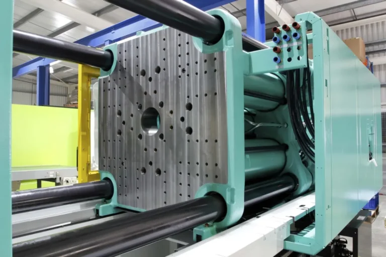
Plastic prototypes usually have another feature, which is that they are plastic parts that need to be produced by molds. Prototypes are one or more physical samples made based on the product appearance 3D drawings or structure 3D drawings without opening a mold. They are used to check the rationality of the appearance or structure.
Why do we need to make prototypes?
In the new product development process, although the specific process details of each company are different, the overall process framework is similar, which includes the prototype trial production stage, that is, the prototype production.
The prototype trial production stage is an indispensable node in the product development process. Its core purpose is to verify the product. Although there are complete 3D drawings and strict drawing review and simulation verification, the physical prototype has irreplaceable value in terms of appearance display effect, physical interaction, ergonomics, functional testing, assembly verification, etc. Prototype trial production can effectively identify problems before mold production, reduce risks and save costs. Specifically:
1) Inspection of appearance design
A prototype is a physical object, visible and tangible. It can clearly reflect the designer’s identity in a physical form, avoiding the risk of “looking good in the drawing but not in the finished product.” Therefore, prototype production is essential during the development of new products and the process of considering product appearance.
2) Inspection structure design
After structural design, the prototype can be assembled after disassembling the parts, so it can intuitively reflect the rationality of the structural design and the difficulty of installation, making it easier to find and solve problems early.
3) Avoid the risk of directly opening the mold
Since mold manufacturing is generally very expensive, the mold of a complete set of products is worth hundreds of thousands or even millions of dollars. If unreasonable structure or other problems are found during the mold making process, the loss can be imagined. Prototype production can avoid such losses and reduce the risk of mold making.
4) Accelerating Product Launch
Since the mold making cycle is long, and the prototype production can usually be completed in about a week, you can use the prototype to promote the product before the mold is developed, or even for early sales and production preparations, so as to occupy the market early.
Common Types of prototypes:
According to the purpose of the prototype, the prototype can be divided into the following types:
1, Functional prototype
It is mainly used to verify the core functions of new products. It follows the principle of “minimum cost verification uncertainty” and does not directly output product prototypes with all functions. Instead, it first makes a single-function prototype that is sufficient to verify a core function, and then verifies and iterates each function one by one, and finally makes a prototype with complete core functions.
Functional prototypes can be designed before or in parallel with the appearance prototype to test, iterate, and refine the mechanical, electrical, and thermal systems that make up the product. These sub-functional modules may look different from the final product, but they include core technologies and functions that need to be developed and tested.

For example, Dyson’s DC39 spherical vacuum cleaner features technical improvements and innovations in noise reduction, turbine nozzles, and cyclonic power. The team created multiple sub-functional prototypes, ranging from internal noise reduction to airflow speed, to verify each function during the testing phase. Only after these verifications were the full prototypes (shown in the lower right corner of the image below) finally developed.
Functional prototypes do not have high requirements for appearance, but have high requirements for the structural size, precision, strength and other performance parameters of the internal core functional modules. Therefore, functional prototypes do not need to be made into outer shells, and internal structural parts do not need to be surface treated with color, texture, etc.
2, Appearance prototype
It is primarily used to verify the overall appearance of a new product, including its dimensions, aesthetics, rationality of disassembly, color matching, material coordination, and surface texture. Appearance prototypes can also provide preliminary verification of ergonomics, user interface, and overall user experience. Furthermore, appearance prototypes can be used for pre-marketing activities such as market promotion and exhibitions.

Appearance prototypes require high attention to detail, but not to internal processing. Appearance prototypes may even be prototypes without core functions, and most of them only design functions related to appearance, such as buttons and lights.
3, Structural prototype
It is mainly used to verify the rationality of product assembly structure, structural interference verification, structural strength, performance testing, cost evaluation (mold opening cost, structural parts cost, assembly cost), etc. Structural prototypes can greatly reduce the risk of direct mold opening.
Structural prototypes can be seen as a combination of function and appearance. Considering manufacturability and commercial feasibility, details become increasingly important at this stage. Structural prototypes may need to be made multiple times, depending on the specific situation. The final prototype is required to achieve an appearance, structure, and function that are close to the actual product. Prototypes at this stage can even be provided to customers for trial experience.

Therefore, all internal details of the structural parts (stops, clips, screw columns, reinforcement ribs, etc.) need to be processed as much as possible according to the 3D drawing. This is the most demanding and difficult type of prototype.


Number of proofing
The number of proofing times is related to the company’s R&D situation (process, funding, R&D strength, etc.) and the manufacturing strength of the prototype factory.
1, Process
Each company has different R&D processes, product complexity, and product requirements, which can be roughly divided into the following categories:
a) Functional prototype, appearance prototype, and structural prototype , mainly for products with complex functions and structures and high appearance requirements, such as home appliances;
b) Functional prototypes and structural prototypes are mainly for products with complex functions and structures but not very high requirements on appearance, such as equipment products;
c) Appearance prototypes and structural prototypes are mainly for products with general functional structures but high appearance requirements, such as 3C products;
d) Structural prototypes , mainly for products with relatively low requirements on functional structure and appearance, such as daily-use products;
Generally speaking, the more complex the product, the more times prototypes are made. Conversely, the simpler the product, the less likely it is that a prototype is needed. For example, for a face plate, a mature and single-function product like this, risks can be identified through drawing review or software simulation verification, and the product can go directly to the mold opening stage without making a prototype.
2, Funding
Funding is a crucial factor, as prototype production is typically not cheap, especially for products with a large number of structural components. For example, at a company I worked for, the initial cost of making a fully functional structural prototype for a product was nearly 100,000 yuan, and they had to produce more than one prototype. Of course, this also depends on the boss’s budget and attitude. If the boss is reluctant to spend, even 10,000 yuan will seem expensive.
3, R&D strength
The company’s strong R&D capabilities allow it to avoid many structural issues during the product design phase, reducing the need for prototype verification. Large companies have technical expertise in diverse areas (mechanics, structure, molds, process, simulation, etc.), while smaller companies may only have mechanical structural engineers, which greatly tests the skills of mechanical structural engineers.
4, Manufacturing strength of the prototype factory
There are simply too many prototype factories, large and small, with varying degrees of manufacturing capabilities. Some have poor machining precision, some have rough hand-finishing, some experience cracking due to paint spraying, and some have long delivery times. Larger prototype factories quote higher prices, while smaller ones offer lower prices. However, concerns about quality can affect the number of prototypes you can produce.

An advertisement: If you have proofing needs, please contact us in the background for a quote. This official account provides quotation consulting services with affordable prices. You are welcome to send us pictures for quotes!
Prototype processing methods
Common prototype processing methods include: machining , sheet metal processing , 3D printing , and lamination. The processing method of the prototype is related to the processing material of the prototype. The processing materials of the prototype are generally plastic materials and metal materials.
1) Commonly used CNC metal materials: aluminum alloy (6061), brass (H62), Q235, 45# steel, etc.;
2) Commonly used sheet metal processing materials: aluminum alloy plates (6061, 5052, 1010, 1060, 6063, etc.), cold rolled plates (SPCC, Q235), galvanized plates (SECC, SGCC), stainless steel plates (SUS304, SUS301, SUS201), etc.;
3) Commonly used CNC plastic materials: ABS, PC, PMMA, POM, PA, PP, etc.
Among them, ABS is the most widely used in the prototype industry, mainly because ABS has good processability and its strength can meet the needs of most prototypes. In addition, the strength after disassembly and bonding will not be greatly affected, and it can adapt to most surface treatment processes.
PC and PMMA are usually used to make transparent parts or light guides. Some people use PC instead of ABS to make prototype shell parts, which will have higher strength. Conventional PMMA is transparent, but it also has milky white color, which is very suitable for light guides.
POM and PA are two materials that are usually used to make parts that need to be wear-resistant, such as gears, shafts and other moving parts. However, these two materials cannot be bonded and need to be processed as a whole.
PA and PP are two materials with strong toughness and are often used in parts that need to be deformed frequently. However, these two materials cannot be bonded and need to be processed as a whole.
4) Commonly used soft rubber materials: silicone, elastomer (TPU, TPE), various types of rubber, etc.
5) Commonly used 3D printing materials: photosensitive resin (normal, tough, heat-resistant, semi-transparent, fully transparent), PA, PA+30%.
1, Machining
Mechanical processing technology, referred to as machining, mainly includes two categories: manual machining and CNC machining .
Manual machining refers to the process of machining various materials by manually operating milling machines, lathes, drilling machines, saws and other mechanical equipment. Manual machining is suitable for small-batch, simple parts production.
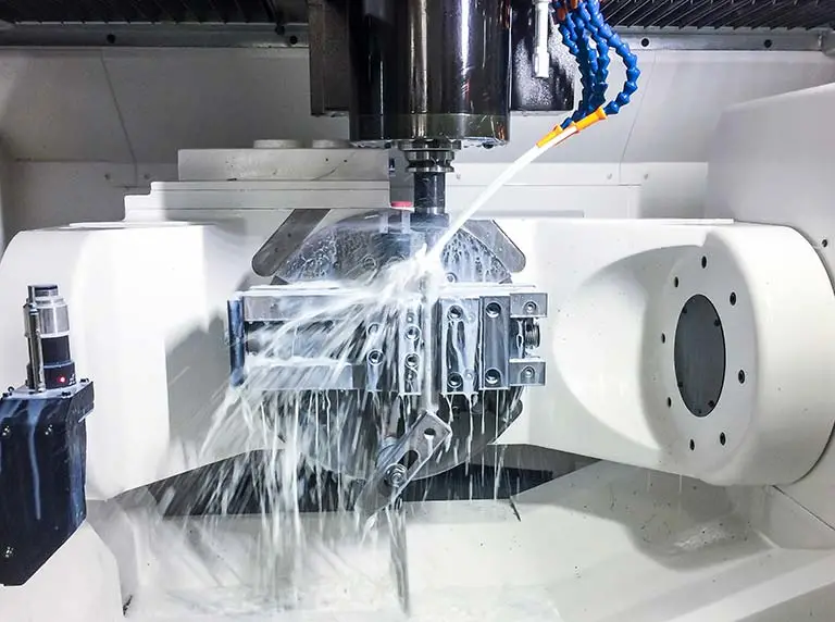
CNC machining (CNC) refers to machining performed by machinists using numerically controlled equipment, including machining centers, turning and milling centers, EDM machines, wire-cutting machines, and thread cutting machines. CNC machining processes workpieces in a continuous manner and is suitable for high-volume, high-precision, and complex-shaped parts.
CNC is widely used in the machining industry and the technology is relatively mature. Currently, CNC milling and turning are the main methods of prototyping, which provide excellent results and precision, but are expensive. CNC can process a wide range of materials, including most metal and plastic parts except for soft plastics.

CNC Milling: 3-axis, 4-axis, and full 5-axis machining 
Other Machining Processes: Wire cutting, EDM (Electrical Discharge Machining), grinding, etc. 
CNC Milling: 3-axis, 4-axis, and full 5-axis machining


Turned parts typically have a smooth surface finish. When turning, the surface finish of cylindrical areas will typically be much smoother than with milling, with a typical CNC turning surface roughness of 1.6-0.8 μm and a typical milling surface roughness of 6.3-1.6 μm.
For general turned parts, turning can basically meet the requirements, while milling will leave knife marks. If necessary, the metal parts can be sandblasted to remove the knife marks and achieve a good matte effect. Therefore, sandblasting is basically a common process for CNC milling of metal parts with exterior design.

Most prototype factories are small and medium-sized, and there are fewer larger ones. The CNC precision of small and medium-sized prototype factories, especially those that focus on plastic processing, is usually not very high. This is mainly because the cost of high-precision CNC equipment is relatively high, which is unaffordable for small prototype factories. Don’t believe it just because the company name says “Precision Prototype Model XX Co., Ltd.”
Another reason is that it is unnecessary. The unnecessary here mainly refers to the fact that plastic prototypes are usually used to verify the appearance or function. Most plastic parts do not require high precision. Moreover, plastic materials are easy to deform, so it is difficult to ensure high precision. Moreover, the final effect of the prototype depends largely on the subsequent manual work, and finally needs to be manually adapted.

For CNC machining of plastic prototypes, the raw materials are usually plates and bars. For parts that are deeper or more complex and cannot be machined by tools, due to the height size restrictions of the plates and to save raw materials, the entire part is usually not CNC machined.
Instead, it is disassembled into several parts and processed separately. Finally, the parts are glued together to form the original shape. After grinding, polishing, and subsequent surface treatment such as oil spraying, the traces of splicing seams are basically invisible from the outside.
Many traces of splicing seams can still be seen from the inside of the parts, but it does not affect the use. The precision of the plastic parts will be further reduced by splicing, but it can be corrected through subsequent manual adaptation. (Note: If there are special requirements that do not allow disassembly processing, you should communicate with the prototype manufacturer in advance).

In view of this, the 3D drawing of the plastic prototype may not meet the conventional mold release or tool cutting requirements. Complex models can be made by disassembling parts during processing. However, this is not a reason for structural engineers to be lazy. This is just a cost-saving way to quickly verify the appearance or function. The subsequent structural verification prototype still depends on the final structural 3D drawing.
Metal machined parts have their own limitations because they cannot be disassembled and processed and then bonded together like plastic parts (unless they are designed to be welded structures). For example, internal undercuts cannot be processed with conventional tools and require special tools. Obviously, the processing fee will not be cheap.

It is understood that most client companies do not have very clear requirements for the accuracy of hand panels (except for a few special parts). They are more concerned about price. As the saying goes, you get what you pay for. Price is usually one of the biggest factors affecting client’s decision-making. The other is the visible and intangible relationship.
Therefore, whether it is plastic parts or metal parts, if there is a need for high-precision processing, it is recommended to find a more professional machining manufacturer. Regarding this point, I have stepped on many pitfalls.
2, Sheet metal processing
Sheet metal processing includes traditional cutting, blanking, bending and forming processes, as well as various cold stamping die forming and post-processing processes.
 Cutting/Punching: Laser cutting, CNC punching
 Bending/Forming: Bending machines, stamping forming
 Post-processing: Hole extruding, riveting, welding


Since the number of sheet metal prototypes used is usually not large, cold stamping die forming is rarely involved. Instead, bending technology is used, followed by welding, polishing and other processes.
However, the bending process has certain limitations on the shape. Parts with streamlined surfaces are not suitable for bending, such as automotive panels, which can only be formed using stamping dies. The bending process is suitable for square product shapes and can allow a certain amount of rounded corners.

Since sheet metal parts are made of sheet metal, the prerequisite for bending sheet metal parts is that they must be able to be unfolded.

If it cannot be unfolded, it can be split into multiple parts and then assembled or welded.

The following basically covers most of the sheet metal processing technologies:
1) Riveting: refers to the process of using a punch or hydraulic press to firmly press fasteners such as rivet nuts, rivet screws or rivet nut standoffs onto the workpiece.
2) Riveting: refers to the process of first countersinking the workpiece and then using a punch or hydraulic press to firmly press the rivet nut onto the workpiece.
3) Pulling: refers to the process of firmly attaching a plug-in rivet nut (POP) or other fasteners to a workpiece using a pull-in gun, similar to riveting.
4) Riveting: refers to the process of using a rivet gun as a tool to tightly connect two or more workpieces with rivets.
5) Riveting: The process of connecting two or more workpieces face to face with rivets. If it is countersunk riveting, the workpiece needs to be countersunk first.
6) Corner cutting: refers to the process of cutting the corners of the workpiece using a mold on a punch press or hydraulic press.
7) Bending: refers to the process of forming the workpiece by a bending machine.
8) Forming: refers to the process of deforming the workpiece using a mold on a conventional punch press or other equipment.
9) Shearing: refers to the process of obtaining rectangular workpieces by shearing machines.
10) Blanking: refers to the process of cutting the workpiece by laser or punching by CNC punching machine.
11) Blanking: refers to the process of using mold processing on ordinary punching machines or other equipment to obtain the shape of the product.
12) Punching: refers to the process of machining holes in workpieces using ordinary punching machines and molds.
13) Embossing: refers to the process of using a mold on a punch press or hydraulic press to form a convex shape on the workpiece.
14) Punching and tearing: also called “punching bridge”, refers to the process of using a die on a punch press or hydraulic press to form the workpiece into a bridge-like shape.
15) Hole punching: also called “flanging”, refers to the process of using a mold on an ordinary punching machine or other equipment to flip up the edge of a round hole on the workpiece.
16) Tapping: refers to the process of machining internal threads on a workpiece.
17) Leveling: refers to the process of using other equipment to level the workpiece if it is uneven before or after processing.
18) Backthreading: refers to the process of repairing the threads of a pre-tapped workpiece for the second time.
19) Drilling: refers to the process of drilling holes in a workpiece using a drill bit on a drilling machine or milling machine.
20) Chamfering: refers to the process of processing the sharp corners of the workpiece using molds, files, grinders, etc.
21) Stamping: refers to the process of using a mold to punch out text, symbols or other impressions on a workpiece.
22) Countersinking: refers to the process of machining a tapered hole on a workpiece to accommodate fasteners such as countersunk screws.
23) Flattening: refers to the process of making a workpiece with a certain shape transition to a flat surface.
24) Mesh punching: refers to the process of punching mesh holes on a workpiece using a mold on a conventional punching machine or a CNC punching machine.
25) Hole expansion: refers to the process of using a drill or milling cutter to process a small hole on a workpiece into a larger hole.
Only large prototype factories are capable of producing both plastic and sheet metal prototypes; small and medium-sized factories generally specialize in specialized areas, such as plastic, machined metal, and sheet metal.
Sometimes, a plastic prototype factory you contact may claim they can produce machined metal or sheet metal parts, but they often outsource the work to hardware factories. This may be somewhat costly, but the advantage is that if your prototype includes both plastic and hardware components, you avoid the hassle of separate processing.
Furthermore, if the plastic and hardware components need to be compatible, the plastic prototype factory will handle this for you, reducing assembly issues after delivery from two different factories.
3, 3D printing
How are the plastic or metal objects we encounter in our daily lives made? From raw materials to finished product, an object undergoes one or more different processing and manufacturing processes. The three most common processing and manufacturing processes are as follows:
Subtractive manufacturing processes
Subtractive manufacturing utilizes separation methods to systematically separate parts of a material from a substrate to create a desired shape. Traditional machining methods such as turning, milling, planing, and grinding all fall under this subtractive manufacturing process. Subtractive manufacturing is currently the most fundamental process in the manufacturing industry.
Additive manufacturing process
Additive manufacturing (AM) refers to a manufacturing process that utilizes various mechanical, physical, and chemical methods to systematically add materials to achieve the desired part design. Rapid prototyping (RPT) is a prime example of AM. It represents a breakthrough in traditional manufacturing methods, enabling the rapid production of parts of any complexity, making it a highly promising new manufacturing technology.
Equal material manufacturing process
Isocratic manufacturing utilizes the formability (such as plasticity) of a material to form an object under specific external constraints (boundary constraints or external forces). Traditional casting, forging, powder metallurgy, sheet metal stamping, and injection molding all fall under this category. Because these processes simply transform the material from one form to another during the production process, without increasing or decreasing the amount of material, they are termed isocratic manufacturing. Isocratic manufacturing is currently the most widely used method for mass production in the manufacturing industry.
3D printing is an additive manufacturing process and a type of rapid prototyping technology. It uses a digital model file as the basis and uses bondable materials such as powdered metal or plastic to construct objects through layer-by-layer printing.
To put it in a more literal way, a regular printer outputs a 2D image or graphic digital file onto paper using ink. A 3D printer, on the other hand, outputs a thin layer (physically of a certain thickness) of a solid raw material (such as metal, ceramic, plastic, sand, etc.), which is then repeatedly stacked layer by layer to ultimately create a 3D object. Therefore, when outputting a single layer, the process of 3D printing is similar to that of inkjet printing. Just as building a house is constructed brick by brick, 3D-printed objects are constructed from the raw materials one grain at a time.

Types of 3D printing processes:
There are many types of existing 3D printing equipment, and each different device corresponds to different printing materials, thus dividing different 3D printing processes.
| Material Form | Manufacturing Process | Printing Materials |
| Liquid | Stereolithography (SLA) | Photopolymer Resin |
| Digital Light Processing (DLP) | Photopolymer Resin | |
| Powder | Three-Dimensional Printing (3DP) | Polymer Materials, Wax |
| Plaster-Based 3D Printing (PP) | UV-curable Ink | |
| Selective Laser Sintering (SLS) | Thermoplastics, Metal Powder, Ceramic Powder | |
| Selective Heat Sintering (SHS) | Thermoplastic Powder | |
| Direct Metal Laser Sintering (DMLS) | Nickel/Cobalt/Iron-based Alloys, Carbide Composites, Oxide Ceramics | |
| Electron Beam Melting (EBM) | Titanium Alloy, Stainless Steel, etc. | |
| Selective Laser Melting (SLM) | Nickel Alloy, Titanium Alloy, Cobalt-Chromium Alloy, Stainless Steel, Aluminum, etc. | |
| Filament | Fused Deposition Modeling (FDM) | Thermoplastics, Low-melting-point Metals, Food-grade Materials |
| Electron Beam Freeform Fabrication (EBF) | Titanium Alloy, Stainless Steel, etc. | |
| Sheet | Laminated Object Manufacturing (LOM) | Paper, Metal Foil, Plastic Film |
| Powder/Wire | Laser Engineered Net Shaping (LENS) | Metal Powders (typically) |
The three most commonly used are:
1, Fused Deposition Modeling (FDM)
A filament of hot-melt material (usually ABS or PLA) is heated and melted, then extruded through an extruder with a fine nozzle. The molten filament then bonds to the previous layer of material. After each layer of material is deposited, the worktable descends by a predetermined thickness, and the process repeats until the part is fully formed.

Advantages and disadvantages of FDM process:
Key Benefits:
1) The operating environment is clean and safe, and the materials are non-toxic. It can be carried out in offices and homes without the risk of generating toxic gases or chemical pollution.
2) No expensive components such as lasers are required, so the price is low.
3) The raw material is in the form of reel wire, which saves space and is easy to carry and replace.
4) The material utilization rate is high, there are many alternative materials, and the price is relatively cheap.
Main disadvantages:
1) The surface is rough after forming and requires subsequent polishing.
2) The speed is slow because the nozzle performs mechanical movement.
3) Materials are needed as a supporting structure.

2, Stereolithography (SLA) process
Using photosensitive resin (utilizing the characteristics of liquid photosensitive material) as the processing material, under computer control, the ultraviolet laser beam (ultraviolet light wavelength: 250nm~400nm) scans point by point along the trajectory of each layered cross-sectional contour. The thin layer of resin in the scanned area undergoes photopolymerization reaction and then solidifies to form a thin layer cross-section of the workpiece (from point to line, from line to surface).
After each layer is cured, the work platform moves a layer thickness and a new layer of photosensitive resin is placed on the previously cured resin for scanning and curing. This cycle repeats, with each new layer adhering to the previous one until the part is complete.

Advantages and disadvantages of SLA process:
Key Benefits:
1) SLA can produce parts with high dimensional accuracy and complex details.
2) SLA parts have a very smooth surface finish, making them ideal for exterior prototypes.


3) The versatility of SLA materials. In addition to ordinary resins, there are resins with other properties to choose from, such as transparent, tough and temperature-resistant resins.

Main disadvantages:
1) SLA parts are usually brittle and not suitable for force-bearing functional prototypes.
2) Poor weather resistance: When parts are exposed to sunlight, the mechanical properties and appearance of SLA parts will degrade over time.
3) Support structures are always required, and post-processing is necessary to remove the marks left on the SLA parts.
3, Selective Laser Sintering (SLS) process
Using a high-energy infrared laser as the energy source, the evenly layered powder material on the workbench is scanned and melted within a selected area according to the layered outline of the product model output by the computer. The powder within the scanned area is melted by the laser beam, forming a sintered layer. After sintering layer by layer, the excess powder is removed to obtain the product prototype. (The process utilizes the melting of low-melting-point metals or binders to bond high-melting-point metal or non-metallic powders together.)
Compared to other 3D printing technologies, SLS’s most significant advantage lies in its wide range of molding materials. Theoretically, any powder material capable of forming an atomic bond upon heating can be used as an SLS molding material. Currently, materials successfully processed by SLS include paraffin wax, polymers (PC, nylon, PE, PP, etc.), metals, ceramic powders, and composite powders.
Advantages and disadvantages of SLS process:
Key Benefits:
1) A wide range of materials can be used. Available materials include polymers, metals, ceramics, gypsum, nylon, and other powder materials. Metal powder materials, in particular, are currently one of the hottest developments in 3D printing technology.
2) Parts manufactured using SLS printing technology have excellent mechanical properties and strength similar to injection molded parts.
3) High precision. Generally, the tolerance of the workpiece can reach (0.05-2.5) mm.
4) No support structure required. The overhanging layers created during the stacking process can be directly supported by the unsintered powder; this makes SLS ideal for constructing complex geometries such as internal features, undercuts, thin walls, and recessed features.
5) High material utilization rate. Since it does not require support or a base, it has the highest material utilization rate among the common 3D printing technologies and is relatively inexpensive.
6) SLS has become a popular choice for engineers for functional prototyping and a cost-effective alternative to injection molding for limited or transitional production.
Main disadvantages:
1) Rough surface. Since the raw materials are in powder form, the prototype is constructed by heating and melting the powder layer to achieve layer-by-layer bonding. Therefore, the prototype surface is strictly speaking in powder form, and the surface quality is not high.
2) There is an odor during the sintering process. In the SLS process, the powder layer needs to be heated by the laser to reach a melting state. The polymer material or powder particles will volatilize and emit odorous gases during laser sintering.
3) It is not possible to directly mold high-performance metal and ceramic parts, and warping and deformation are prone to occur when molding large-sized parts.
4) Long processing time. Before processing, there is a 2-hour preheating time. After the part is built, it takes 5 to 10 hours to cool down before it can be removed from the powder tank.
5) Due to the use of high-power lasers, in addition to the equipment cost itself, many auxiliary protection processes are also required. The overall technical difficulty is high, and the manufacturing and maintenance costs are very high, which ordinary users cannot afford.

Each 3D printing technology has its own advantages, disadvantages, and requirements, suited to different applications and businesses. The table below compares some key factors of the three 3D printing technologies: FDM, SLA, and SLS.
| Items | Fused Deposition Modeling (FDM) | Stereolithography (SLA) | Selective Laser Sintering (SLS) |
| Resolution | ★★☆☆☆ | ★★★★★ | ★★★★☆ |
| Accuracy | ★★★★☆ | ★★★★★ | ★★★★★ |
| Surface finish | ★★☆☆☆ | ★★★★★ | ★★★★☆ |
| Yield | ★★★★☆ | ★★★★☆ | ★★★★★ |
| Design complexity | ★★★☆☆ | ★★★★☆ | ★★★★★ |
| Ease of use | ★★★★★ | ★★★★★ | ★★★★☆ |
| advantage | Rapid and low-cost consumption of machines and materials | High value, high precision and smooth surface suitable for a variety of functional applications | Robust functional components with high design freedom and no need for supporting structures |
| insufficient | Low precision, poor details, limited design compatibility | Avoid long-term exposure to ultraviolet rays | Limited choice of materials with rough surfaces |
| application | Low-cost rapid prototyping of basic proof-of-concept models | Functional prototyping Models, molds, and tools for dental applications Jewelry prototyping and casting pattern making | Functional prototyping Short-run, interim or custom manufacturing |
| Print volume | Up to 300 × 300 × 600 mm (desktop and desktop 3D printers) | Up to 300 × 335 × 200 mm (desktop and desktop 3D printers) | Up to 165 × 165 × 300mm (desktop industrial 3D printer) |
| Material | Standard thermoplastics such as ABS, PLA and their various blends. | A wide range of resins (thermosets). Standard resins, engineering resins (ABS-like, PP-like, flexible, heat-resistant), castable resins, dental resins, and medical resins (biocompatible resins). | Engineering thermoplastics. Nylon 11 Powder, Nylon 12 Powder, and their composites. |
| Training | Light-scale training on molding setup, machine operation, and surface preparation; medium-scale maintenance training. | Plug and play. Small-scale training for molding setup, maintenance, machine operation and surface treatment. | Medium-scale training in molding setup, maintenance, machine operation, and surface preparation. |
| Facility requirements | Air-conditioned environment or a ventilation environment customized for desktop printers. | Desktop printers are suitable for office environments. | Shop floor environments with moderate space requirements for desktop systems. |
| auxiliary equipment | Support removal system (optionally automated), surface preparation tools for printers equipped with soluble supports. | Post-curing station, cleaning station (optionally automated), surface treatment tools. |
3D printing costs include more than just the initial equipment cost. 3D printing materials and labor costs significantly impact the cost per part. A comparison of 3D printing costs using FDM, SLA, and SLS technologies is shown below:
| Items | Fused Deposition Modeling (FDM) | Stereolithography (SLA) | Selective Laser Sintering (SLS) |
| Equipment costs | Budget printers and 3D printer kits start at a few hundred dollars. Higher-quality mid-range desktop printers start around $2,000, and industrial systems start at $15,000. | Professional desktop printers start at $3,500, large desktop printers start at $10,000, and large industrial printers start at $80,000. | Prices start at $18,500 for desktop industrial systems and $100,000 for traditional industrial printers. |
| Material costs | Most standard and engineered filaments cost $50–150/kg, and support materials cost $100–200/kg. | Most standard and engineered resins cost $149–200 per liter. | Nylon costs $100/kg. SLS does not require support structures, and unfused powder can be reused to reduce material costs. |
| Labor demand | Manual support removal (most supports can be removed automatically with industrial systems that use soluble supports) and lengthy post-processing are required to achieve a high-quality surface finish. | Cleaning and post-curing (most of the process is automated) are performed with simple post-processing to remove support marks. | Perform a simple clean to remove excess powder. |
In general, FDM technology is suitable for beginners and low-cost applications, SLA technology is suitable for applications requiring high precision and details, and SLS technology is suitable for functional parts and applications of special materials. Choosing the right technology depends on factors such as project requirements, budget, and material properties.
As a new type of processing and manufacturing technology, what are the advantages and disadvantages of 3D printing technology compared with traditional manufacturing processes?
Advantages of 3D printing:
1.Unlimited design space
Traditional manufacturing processes are incapable of processing parts with complex geometric structures (such as those with complex internal topologies or cavities), requiring the parts to be disassembled, processed separately, and then reassembled. 3D printing, however, breaks down parts into layers of 2D regions, making it possible to process parts of any complexity. The accuracy of the process depends solely on the smallest material particle size the printer can produce. This is the greatest advantage of 3D printing, allowing designers to create arbitrarily complex geometries, creating an unlimited design space.
2. Cost savings
1) Cost. Traditional manufacturing equipment is large and expensive, requiring high-level skills to operate. For example, CNC equipment requires programming and a skilled operator. 3D printers (such as FDM 3D printers) are compact and inexpensive, some already available in homes, and are easy to use. Unlike expensive machining equipment or molds, 3D printing requires only a digital file to create a part.
2) Material cost. 3D printing belongs to additive manufacturing, while traditional machining belongs to subtractive manufacturing. Subtractive manufacturing produces more waste, while 3D printing has a high material utilization rate and produces very little waste.
3) Processing costs. In traditional manufacturing, the more complex an object’s shape, the higher the manufacturing cost. However, with 3D printers, the cost of manufacturing complex parts does not increase accordingly. The time, raw materials, and cost required to manufacture a complex part are similar to those required to print a simple block of the same size.
4) Time cost. Traditional manufacturing processes involve a series of steps, including programming, clamping, tool setting, cleaning, and polishing. 3D printing eliminates these processes, and the main processing time is spent on printing, which is related to the volume of the part. Therefore, for low-volume parts, 3D printing can save processing time. For example, when creating a prototype of a product’s exterior, 3D printing takes much less time than traditional CNC production, significantly shortening product development time.
3, Integrated molding
3D printers also have the ability to form parts in one piece, eliminating the need for assembly and shortening delivery times. Traditional manufacturing processes would require disassembling multiple parts, which would take additional time to assemble. While this feature of 3D printing is quite practical for certain structures, we rarely use it because we’re used to traditional design methods.
4, Keep the original structure
3D printing can preserve a part’s original fine features (within a certain precision range). However, with traditional CNC machining, due to tool radius, many details cannot be machined in one go, requiring additional processes for corner cleaning. This is a common situation: the drawings clearly show no interference, but the final prototypes may exhibit interference after assembly.
Disadvantages of 3D printing:
1,slow molding time:
The molding time is slow. For large parts, such as plastic prototype parts, they can be disassembled and processed separately by multiple CNC machines and finally spliced together. However, 3D printing can only be printed on one 3D printer. Obviously, in this case, the time used for 3D printing processing is not much better than traditional manufacturing processes. Therefore, 3D printing is more suitable for small and medium-sized parts.
2, Low precision:
Low precision compared to CNC, and it is also related to factors such as printer quality, part design, materials, printing parameters, etc.
FDM: The accuracy of desktop FDM printers is about ±0.5mm, and the accuracy of industrial FDM printers is about ±0.2mm.

SLA: The accuracy is about ±0.1mm, and the accuracy of professional resin 3D printers is about ±0.05mm.

SLS: Usually uses nylon powder, with an accuracy of about ±0.3mm.
3, Limited material selection:
There are few types of materials. The materials suitable for 3D printing are limited, and materials with better performance are usually more expensive. CNC processing can process a wide range of materials. Except for soft rubber materials, almost most hard materials can be processed by CNC.
4, Poor surface treatment:
The surface treatment effect is poor . This is because there are differences between 3D printing materials and CNC materials. Generally speaking, the surface polishing effect of 3D printed parts is not as good as that of CNC machined parts. This affects the subsequent surface treatment effects such as painting and electroplating, as well as the adhesion of the coating.
5, Limited size:
The printing platform size of 3D printers is generally not large at present. The size of a single part is limited. When printing large parts, they must be cut into multiple parts and then assembled. Even if large parts can be printed, it is easy to cause deformation and there will be large dimensional errors.
One area where FDM printers have consistently held a dominant position is build volume. Due to the technological differences, developing larger FDM printers is relatively straightforward. There are a number of large-scale FDM solutions on the market suitable for applications requiring large 3D printed parts.
The reverse SLA process behind desktop SLA printers reduces space and costs, but the increased peel force limits material and volume, requiring a strong support structure to successfully print large parts.
Currently, the practical application of 3D printing still falls within the realm of rapid prototyping, enabling companies to create prototypes before formal product production, also known as “prototypes.” Therefore, 3D printing currently serves as a complementary approach to traditional manufacturing, and it will take time for it to become a mainstream manufacturing technology.