Intro
In fields such as high-end molds, aerospace, and precision electronics, many parts require high hardness, complex structures, extremely small tolerances, and a high degree of finish. Traditional cutting processes struggle to meet these stringent requirements, leading to the emergence of electrical discharge machining (EDM), which uses electricity as a tool.
This article will delve into the working principles of electro-discharge machining (EDM), common electrodes, and key factors influencing machining quality. EDM is unique in its ability to “carve” complex geometries without relying on tool hardness or generating mechanical stress.
1, What is the principle of EDM?
Electrospark machining is a non-contact, special machining method based on the conversion of electrical energy into thermal energy.


The basic principles are as follows:
- The electrode (Electrode) and the workpiece (Work-Piece) are connected to the negative and positive poles of the pulse power supply respectively;
- A small gap (Spark-Gap , usually between 0.005 and 0.3 mm ) is maintained between the two and they are immersed in an insulating medium (Dielectric Fluid, such as kerosene or deionized water);
- When the electrode approaches the workpiece and the gap is reduced to a certain value, the working fluid is broken down and high-frequency pulse sparks are generated. This process is called discharge.
- The discharge generates instantaneous high temperature (up to 8000-12000℃), which causes the metal on the workpiece surface to melt or even evaporate ;
- The melted material is quickly cooled and washed away by the working fluid, forming tiny pits;
- By repeating this process, the shape of the electrode is “copied” onto the workpiece, achieving precise forming.

Although there is no direct contact in the entire process, the control of discharge parameters (voltage, current, pulse width, frequency, and duty cycle) is extremely critical, and the use of a CNC system is required to achieve automated processing.
????Core conditions :
- Pulse power supply
- Insulating working fluid
- Automatic feed adjustment device (maintaining constant discharge gap)
2. Commonly used electrodes and their characteristics
The electrode is the “mold mold” in EDM processing. Its material directly affects the processing efficiency, precision and surface quality. Common electrode materials include:
| Electrode materials | Features | Applicable Scenarios |
|---|---|---|
| Copper (pure copper) | Good conductivity, stable discharge, and high surface finish; but low hardness, easy to wear, and high cost | Precision machining, mirror machining, and cavities with high surface requirements |
| graphite | Lightweight, easy to process, fast discharge speed, high temperature resistance, low loss; but it produces a lot of dust and has low strength. | Rough machining, large cavity, complex structure electrode |
| Copper tungsten alloy | Extremely high melting point, extremely low loss, strong resistance to electrical corrosion; expensive | Demand for high-precision, long-life electrodes in aerospace, military, and other industries |
????Selection suggestion : Graphite is commonly used for rough machining, and copper is mostly used for fine machining; complex electrodes can adopt a segmented combination design.
3. Surface quality related
Surface quality is one of the core evaluation indicators of EDM processing and directly affects the functionality and life of parts.
1 Spark position and processing speed
- “Spark position” : In discharge machining, due to the existence of the spark gap, the electrode size needs to be smaller than the machining shape, and the amount of reduction is the spark position.Spark position R = (cavity size – electrode size) ÷ 2

- Machining speed : Generally measured in mm³/min . The greater the EDM energy, the faster the machining speed and the larger the discharge gap. If the spark field is increased, the machining speed (removal rate) can be increased several times. Another important point is that roughing conditions are not only fast but also low-loss. This means that if the spark field is sufficient, high-efficiency and low-loss conditions can be used.
✅ Rule : Use large energy and large spark position for rough machining, and the surface will be rough; use sm
2 How to obtain good surface quality?
In order to obtain good surface quality in a short time, rough machining can be used to remove most of the material, and then fine machining can be performed. To further shorten the processing time, the processing conditions should be adjusted in time.
For example, if the surface roughness after rough machining is Ra5.0μm and the target roughness is Ra0.8μm, multiple transition machining conditions need to be set between rough machining and finish machining.
1) Bottom surface
The bottom surface can be achieved by adjusting the conditions and setting the height, but the side surface cannot be achieved due to the large discharge gap during rough machining.

2) Side machining by translation
In order to process the side, the electrode must be close to the side. The plane movement perpendicular to the processing direction is called translation, and its purpose is to complete the side processing.


3, Effect of 2D translation on accuracy
1) Two-dimensional translation
Two-dimensional translation refers to the small movement of the electrode in circular, square and other trajectories during the machining process, which is used to compensate for the spark position and electrode loss.

2) Circular shaking
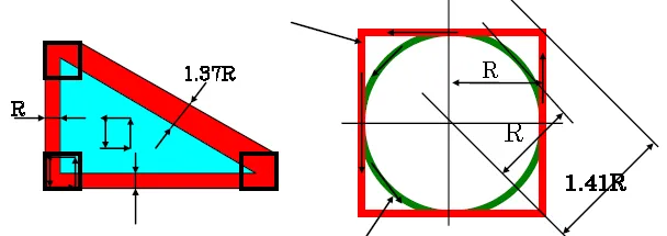
Because the electrode size is smaller than the desired shape, it needs to be expanded in all directions by a radius of R to achieve the target size. This is equivalent to each point performing a circular motion with a radius of R. In the figure below, the straight line is expanded correctly, but the sharp corners are not expanded enough.

As shown in the figure below, for typical shapes, the electrode spark position will reduce the outer corner radius and increase the inner corner radius. Using circular oscillation will produce the correct shape. If the spark position is determined by offset during electrode production, circular oscillation can produce the correct shape and avoid sharp corners. Circular oscillation is a standard oscillation method that prevents overcutting. If you are unfamiliar with oscillation, this method is recommended.

3) Square translation
Corner machining is crucial in EDM. For square or rectangular cavities, square translation is generally preferred over circular translation and is more efficient.
However, using square translation for general shapes can cause problems. As shown in the figure below, in the diagonal area, square translation can cause overcutting, which is most obvious at a 45-degree angle.
4 ,Effect of 3D Translation on Accuracy
1) 3D Translation
3D translation is an upgrade of 2D translation. The electrode swings along a spatial trajectory (e.g., spherical or conical path) in the X/Y/Z directions, simulating a “swaying” motion.
2) Simple bottom shape
For typical spark machines, vertical translation is constant. If the XY plane is circular, the XZ or YZ plane is similar to a square oscillation, with the same base radius and slope. However, due to machining offsets in the spark position R, the base radius and slope are typically reduced. Using a simple bottom electrode shape can easily overcut sharp corners, with the amount of overcut depending on the ratio of the electrode’s spark position R, making overcutting more likely during roughing.
If you want to use the bottom simple shape mode, the bottom corner radius and slope of the electrode must be consistent with the final shape.

3) Complex bottom shape
For electrodes with difficult-to-determine bottom radius or uneven bottoms, a “complex bottom shape” (spherical translation) method is required. Viewed from the side (Z-X or Y-Z plane), the translation path resembles a circle and has no overcutting. This method is suitable for rough machining using large electrodes.

???? High-end EDM equipment generally supports 3D translation function and is widely used in precision fields such as turbine blades and medical molds.
Conclusion: EDM is not just a spark, it is also a fine carving
Although electro-discharge machining (EDM) is not as “visible and tangible” as CNC, it uses electricity as energy, liquid as medium, and time as precision. Through invisible tiny sparks, it completes many precise tasks that are unattainable by traditional processes.