Toolpath Generation
 Zigzag
 Contour
 Spiral
A helical chamfer milling cutter uses a spiral motion, rather than a vertical downward motion. The tool mills helically in the XY plane. It also descends slowly as it moves downward along the Z axis.
This tool path must be tightly controlled. For spiral milling G-code, computer-aided manufacturing (CAM) software, such as Archimedean interpolation, can be used to design the motions, producing perfect lines with every cut.
Tool selection
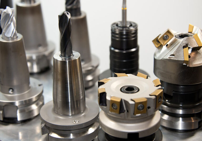
The wrong tool selection can result in scrap. The optimal tool size should be 40%-60% larger than the desired hole size . It also covers the spiral radius of the part.
For holes smaller than 20mm, it’s best to use solid carbide tools. When moving to larger operations, use indexable tools. They’re durable and provide stable performance.
Cutting data
Don’t guess at the feed rate; find the right way to set it. For helical milling, use a Z-axis feed of approximately 20% of the depth of cut. The required ramp angle will need to be adjusted based on the material being used.
For harder steels, a shallow ramp angle of 1° to 3° is sufficient. Softer materials can be cut more aggressively, with a ramp angle of 3° to 10°.
Applicable materials and workpiece scenarios

1, Applicable material types
Cemented carbide and high-strength metals: such as titanium alloys, stainless steel, and high-temperature alloys. The distributed cutting force of spiral milling can reduce tool wear and avoid tool overheating or edge breakage caused by traditional drilling due to high-hardness materials (for example, titanium alloy parts processing in the aerospace field).
Composite and brittle materials: carbon fiber composites, glass fiber, ceramics, etc. Curved cutting paths can reduce vibration and reduce the risk of material cracking or delamination (such as composite hole processing in wind turbine blades).
Non-ferrous metals and soft metals: aluminum alloys, copper alloys, etc. Due to the low cutting force, the surface finish can be improved and the burr problem in traditional processing can be avoided (such as the processing of aluminum alloy shells of automotive parts).
2, Applicable workpiece structure and processing requirements
Deep hole and precision hole processing: When the hole depth to diameter ratio (hole depth/diameter) is large, the axial load of spiral milling is low, which can reduce tool deflection and ensure the straightness of the hole (such as deep hole processing in the mold industry).
Complex contour holes and threaded holes: Tapered holes, stepped holes or threaded holes can be processed without changing tools, and trajectory control can be achieved through programming (such as thread milling of mechanical parts instead of traditional tapping).
Thin-walled parts and easily deformed workpieces: Distributed cutting force can reduce the risk of workpiece deformation and is suitable for thin-walled structural parts in the aerospace field (such as hole processing in aircraft skins).
Application limitations and inapplicable scenarios
1,Material Restrictions
Extremely soft or sticky materials: such as lead, pure rubber, etc. These materials are prone to sticking to the tool, and the chip discharge efficiency of spiral milling may decrease, resulting in worse surface roughness.
Highly hard and brittle materials: such as hardened steel (hardness > 60HRC), carbide blocks, etc. If the cutting parameters are inappropriate, local stress concentration may cause tool edge chipping (coated tools or special processes are required).
2, Workpiece and processing requirements
Small hole processing (diameter < 1mm): The tool diameter of the spiral milling cutter is limited by the hole size. Small-diameter tools have poor rigidity and are prone to vibration. In this case, traditional drilling is more efficient.
Large-scale shallow hole processing: The trajectory planning and programming complexity of spiral milling is higher than that of drilling. When processing shallow holes (such as circuit board holes) in batches, the production efficiency may be lower than that of traditional processes.
Special shapes other than non-circular holes: If the workpiece requires non-circular contours such as square holes and hexagonal holes, spiral milling needs to be combined with interpolation motion, which has low processing efficiency. It is more suitable to use processes such as electrical discharge machining (EDM).
Rough machining with low-precision requirements: For holes with loose tolerance requirements (such as below IT12), the high-precision advantage of spiral milling cannot be realized and the economic efficiency is poor.


