The processing performance of CNC machining centers is very powerful and has a wide range of applications. However, there are some detailed knowledge that our processing personnel need to master when using CNC machining centers. The editor summarizes a lot of information and analyzes in detail the eight steps that you need to be familiar with when using CNC machining centers. Let’s take a look and see if you have overlooked these:
1.Preparation before starting the machine tool
Each time the machine tool is turned on or after the feed is stopped or reset, the machine tool reference should be reset to zero first, so that the machine tool has a reference position for subsequent operations;
2.Workpiece clamping
Before clamping the workpiece, each surface must be cleaned first. No iron filings, dust or oil should be allowed. Use a file or oilstone to remove burrs on the workpiece surface. The height iron used for clamping must be ground on a grinder to make each surface smooth and reliable. The code iron and nut must be fixed to reliably clamp the processed parts. When dealing with some difficult clamping parts, they can be clamped directly on the vise. The machine tool work surface needs to be kept clean, free of iron filings, oil and dust. Iron pads are generally placed at the four corners of the workpiece. For parts with too large a span, a height iron must be placed in the middle.
According to the size of the drawing, use a ruler to check whether the length, width and height of the workpiece are qualified. When clamping the workpiece, according to the clamping and placement method in the programming work instruction, avoid the situation where the machining is not done and the tool head may touch the fixture during machining. After the workpiece is placed on the iron pad, the reference surface of the workpiece should be measured according to the requirements of the drawing. For the workpiece that has been ground, its verticality needs to be checked to see if it is qualified. After the workpiece is measured, the nut must be tightened to prevent the clamping from being unreliable and causing the workpiece to be unique during processing. Measure it again to make sure that the error does not exceed the specified value after clamping;
3.Number of workpiece collisions
The clamped parts can be counted using a counting head to determine the reference zero position. The counting head can use photoelectric and mechanical methods. There are two methods: center counting and single-side counting. The steps of center counting are as follows:
The photoelectric type is stationary, while the mechanical type rotates at 450-600ipm. The X-axis of the worktable is manually moved in the middle of the touch count, and the touch head touches the side of the workpiece. When the touch head just touches the workpiece and the red light turns on, the relative coordinate value of this point is set to 0. Then the X-axis of the worktable is manually moved to let the touch head touch the other side of the workpiece. When the touch head touches the workpiece, the relative coordinate at this time is recorded. According to the relative value, the diameter of the touch head is subtracted to check whether the length of the workpiece meets the requirements on the drawing.
Divide this relative coordinate number by 2, and the value obtained is the middle value of the workpiece X axis. Move the worktable to the middle value on the X axis, and set the relative coordinate value of the X axis at this point to 0. This point is the zero point on the workpiece X axis. Carefully record the mechanical coordinate value of the workpiece X axis 0 point in one of G54-G59, let the machine tool determine the 0 point on the workpiece, and check the correctness of the data again. The steps for setting the workpiece Y axis 0 point are the same as the operation of the X axis.
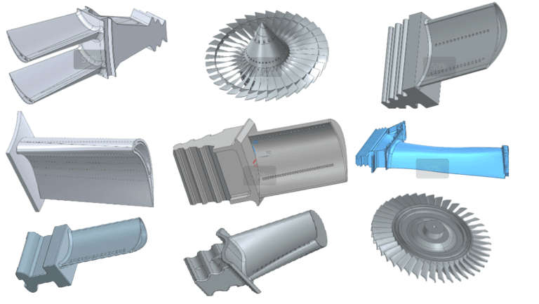
4.Workpiece CAM software programming
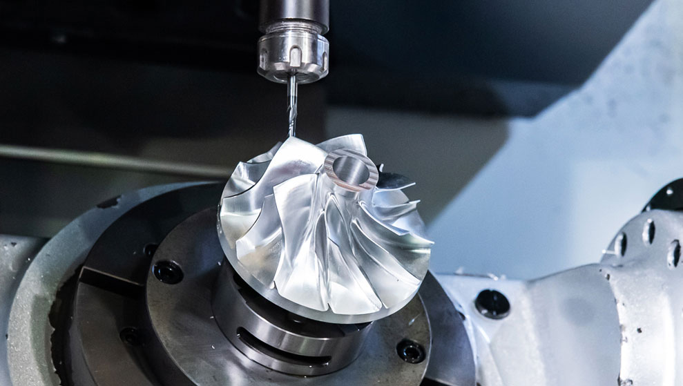
The programmer selects the parts to be processed, programs them through the CAM software UG, generates tool paths, performs interference checks through the UG simulation module, and processes them after the interference checks to generate safe and stable NC codes, which are then transmitted to the workshop and then put into operation.
5.Prepare all tools according to the programming instructions
According to the tool data in the programming work instruction, replace the tool to be processed, let the tool touch the height measuring device placed on the reference surface, and set the relative coordinate value of this point to zero when the red light of the measuring device is on. Move the tool to a safe place, manually move the tool down 50mm, and set the relative coordinate value of this point to zero again. This point is the zero position of the Z axis.
Record the mechanical coordinate Z value of this point in one of G54~G59. This completes the zero position setting of the workpiece X, Y, and Z axes. Check the correctness of the data again.
For single-side contact counting, touch one side of the workpiece X and Y axis in the same way as above, and offset the relative coordinate value of X and Y axis at this point by the radius of the contact counting head, which is the zero position of X and Y axis. Finally, mark the mechanical coordinate of X and Y axis in one of G54~G59. Carefully check the correctness of the data again.
Check the correctness of the zero point, move the X and Y axes to the side of the workpiece, and visually check the correctness of the zero point according to the size of the workpiece. Copy the program file to the computer according to the file path in the programming work instruction.
6.Setting of processing parameters
The setting of spindle speed during processing: N=1000×V/(3.14×D)
N: spindle speed (rpm/min)
V: cutting speed (m/min)
D: tool diameter (mm)
Processing feed speed setting: F=N×M×Fn
F: Feed speed (mm/min)
M: Number of tool edges
Fn: Cutting amount of tool (mm/revolution)
Cutting amount per blade setting: Fn=Z×Fz
Z: Number of cutting edges of the tool
Fz: Cutting amount per cutting edge of the tool (mm/revolution)
7.Start processing
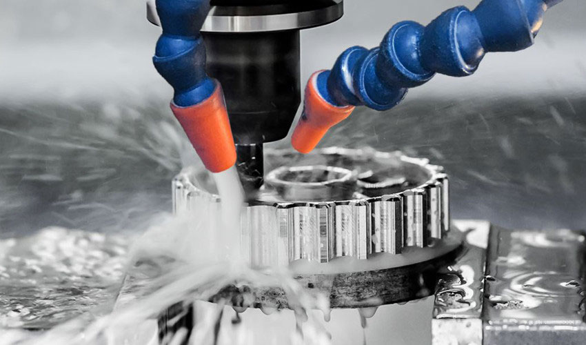
At the beginning of each level of machining, you need to carefully check whether the tool you need to use is the one set in the programming manual. When starting processing, adjust the feed speed to the minimum. You need to concentrate when performing rapid positioning and feeding in a single section. Your hand should be on the stop button. If an abnormality occurs, stop immediately. You need to observe the direction of tool movement and ensure safe feeding, then slowly increase the feed speed to the appropriate position. At the same time, you need to add coolant or cold air to the tool and workpiece. Do not be too far away from the control panel during rough machining. If there is any abnormality, you should stop and check it immediately. After rough machining, pull the table once to make sure the workpiece is not loose. If so, you need to recalibrate the number of collisions. During the machining process, continuously optimize the machining parameters to achieve better machining results.
Because this process is a critical process, after the workpiece is processed, it is necessary to measure its main dimension values to see if they are consistent with the drawing requirements. If there are any problems, they should be reported to the on-duty leader or program editor in a timely manner for inspection and resolution. It can only be removed after passing the self-inspection and must be sent to the inspector for special inspection.
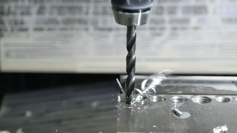
Processing Type
Hole processing: Before drilling holes on the machining center, be sure to use a center drill to locate them first, then use a drill bit that is 0.5 to 2 mm smaller than the drawing size to drill, and then use a suitable drill bit for finishing;
Boring: The workpiece should be positioned with a center drill first, then drilled with a drill bit 1-2mm smaller than the drawing size, and then processed with a rough boring cutter (or milling cutter) until only about 0.3mm machining allowance is left on one side, and finally fine boring is performed with a pre-sized fine boring cutter. The final fine boring allowance should not be less than 0.1mm;
Reaming: When reaming a workpiece, first use a center drill to position it, then use a drill bit that is 0.5-0.3mm smaller than the drawing size to drill the hole, and finally use a reamer to ream the hole. When reaming, pay attention to controlling the spindle speed within 70-180rpm/min.
Direct numerical control (DNC) operation: Before DNC machining, you must first clamp the workpiece, set the zero position, and set the parameters. Open the machining program to be transferred in the computer for inspection, then let the computer enter the DNC state and enter the correct machining program file name. Press the TAPE key and the program start key on the processing machine, and the machine tool controller will flash the word LSK. Press the Enter keyboard on the computer to perform DNC machining.
8.Scope and content of self-inspection by processing personnel
Before processing, the processing personnel must read the contents on the process card clearly, know the parts and shapes of the workpiece to be processed, and the dimensions marked on the drawings, and know the processing content of the next step;
Before clamping the workpiece, the size of the blank material needs to be measured to see if it meets the requirements of the drawing. When clamping the workpiece, it is necessary to check whether its placement is consistent with the programming work instructions;
After the rough machining is completed, self-inspection is carried out so that the erroneous data can be adjusted in time. The self-inspection content is mainly the position and size of the machining filling;
Precision machining can only be carried out after self-inspection of rough machining. After precision machining, the operator should self-inspect the shape and size of the machining position. For the machining position of the vertical surface, check its basic length and width. For the machining position of the inclined surface, check the dimensions marked on the drawing. After the machining personnel complete the self-inspection and confirm that it is in line with the drawing and process requirements, they can unload the workpiece and send it to the inspector for special inspection;
Summary
The above are the eight basic steps of using CNC machining center. Let’s summarize them together. They mainly include preparation before starting the machine, clamping of workpieces, number of workpiece collisions, workpiece CAM software programming, preparation of relevant tools according to the operation instructions, setting of machining parameters, starting the machine and self-inspection after machining. I hope it can be helpful to you!